A lot of people have been asking how they can continue to use air print capabilities even with their printers being in a separate VLAN from the end user devices. This video goes into detail on how you can do that.
A lot of people have been asking how they can continue to use air print capabilities even with their printers being in a separate VLAN from the end user devices. This video goes into detail on how you can do that.
Troubleshooting
Tracking SD-WAN sessions
You can check the destination interface in FortiView in order to see which port the traffic is being forwarded to.
The example below demonstrates a source-based load-balance between two SD-WAN members.
For information on other features of FortiView, see FortiView on page 91.
Understanding SD-WAN related logs
This topic lists the SD-WAN related logs and explains when the logs will be triggered.
Health-check detects a failure:
34: date=2019-03-23 time=17:26:06 logid=”0100022921″ type=”event” subtype=”system” level=”critical” vd=”root” eventtime=1553387165 logdesc=”Routing information changed” name=”test” interface=”R150″ status=”down” msg=”Static route on interface R150 may be removed by health-check test. Route: (10.100.1.2->10.100.2.22 ping-down)”
32: date=2019-03-23 time=17:26:54 logid=”0100022921″ type=”event” subtype=”system” level=”critical” vd=”root” eventtime=1553387214 logdesc=”Routing information changed” name=”test” interface=”R150″ status=”up” msg=”Static route on interface R150 may be added by health-check test. Route: (10.100.1.2->10.100.2.22 ping-up)”
Health-check has an SLA target and detects SLA qualification changes:
5: date=2019-04-11 time=11:48:39 logid=”0100022923″ type=”event” subtype=”system” level=”notice” vd=”root” eventtime=1555008519816639290 logdesc=”Virtual WAN Link status” msg=”SD-WAN Health Check(ping) SLA(1): number of pass members changes from 2 to 1.”
2: date=2019-04-11 time=11:49:46 logid=”0100022923″ type=”event” subtype=”system” level=”notice” vd=”root” eventtime=1555008586149038471 logdesc=”Virtual WAN Link status” msg=”SD-WAN Health Check(ping) SLA(1): number of pass members changes from 1 to 2.”
SD-WAN calculates a link’s session/bandwidth over/under its ratio and stops/resumes traffic:
3: date=2019-04-10 time=17:15:40 logid=”0100022924″ type=”event” subtype=”system” level=”notice” vd=”root” eventtime=1554941740185866628 logdesc=”Virtual WAN Link volume status” interface=”R160″ msg=”The member(3) enters into conservative status with limited ablity to receive new sessions for too much traffic.” l When SD-WAN calculates a link’s session/bandwidth according to its ratio and resumes forwarding traffic:
1: date=2019-04-10 time=17:20:39 logid=”0100022924″ type=”event” subtype=”system” level=”notice” vd=”root” eventtime=1554942040196041728 logdesc=”Virtual WAN Link volume status” interface=”R160″ msg=”The member(3) resume normal status to receive new sessions for internal adjustment.”
The SLA mode service rule’s SLA qualified member changes:
14: date=2019-03-23 time=17:44:12 logid=”0100022923″ type=”event” subtype=”system” level=”notice” vd=”root” eventtime=1553388252 logdesc=”Virtual WAN Link status” msg=”Service2() prioritized by SLA will be redirected in seq-num order 2(R160) 1(R150).” 15: date=2019-03-23 time=17:44:12 logid=”0100022923″ type=”event” subtype=”system” level=”notice” vd=”root” eventtime=1553388252 logdesc=”Virtual WAN Link status” interface=”R150″ msg=”The member1(R150) SLA order changed from 1 to 2. ”
16: date=2019-03-23 time=17:44:12 logid=”0100022923″ type=”event” subtype=”system” level=”notice” vd=”root” eventtime=1553388252 logdesc=”Virtual WAN Link status” interface=”R160″ msg=”The member2(R160) SLA order changed from 2 to 1. ”
1: date=2019-03-23 time=17:46:05 logid=”0100022923″ type=”event” subtype=”system” level=”notice” vd=”root” eventtime=1553388365 logdesc=”Virtual WAN Link status” msg=”Service2() prioritized by SLA will be redirected in seq-num order 1(R150) 2(R160).” 2: date=2019-03-23 time=17:46:05 logid=”0100022923″ type=”event” subtype=”system” level=”notice” vd=”root” eventtime=1553388365 logdesc=”Virtual WAN Link status” interface=”R160″ msg=”The member2(R160) SLA order changed from 1 to 2. ” 3: date=2019-03-23 time=17:46:05 logid=”0100022923″ type=”event” subtype=”system” level=”notice” vd=”root” eventtime=1553388365 logdesc=”Virtual WAN Link status” interface=”R150″ msg=”The member1(R150) SLA order changed from 2 to 1. ”
The priority mode service rule member’s link status changes:
1: date=2019-03-23 time=17:33:23 logid=”0100022923″ type=”event” subtype=”system” level=”notice” vd=”root” eventtime=1553387603 logdesc=”Virtual WAN Link status” msg=”Service2() prioritized by packet-loss will be redirected in seq-num order 1(R150) 2 (R160).”
2: date=2019-03-23 time=17:33:23 logid=”0100022923″ type=”event” subtype=”system” level=”notice” vd=”root” eventtime=1553387603 logdesc=”Virtual WAN Link status” interface=”R160″ msg=”The member2(R160) link quality packet-loss order changed from 1 to 2.
”
3: date=2019-03-23 time=17:33:23 logid=”0100022923″ type=”event” subtype=”system” level=”notice” vd=”root” eventtime=1553387603 logdesc=”Virtual WAN Link status” interface=”R150″ msg=”The member1(R150) link quality packet-loss order changed from 2 to 1. ” l When priority mode service rule member’s link status changes. In this example R160 changes to better than R150, and both are still alive:
6: date=2019-03-23 time=17:32:01 logid=”0100022923″ type=”event” subtype=”system” level=”notice” vd=”root” eventtime=1553387520 logdesc=”Virtual WAN Link status” msg=”Service2() prioritized by packet-loss will be redirected in seq-num order 2(R160) 1 (R150).”
7: date=2019-03-23 time=17:32:01 logid=”0100022923″ type=”event” subtype=”system” level=”notice” vd=”root” eventtime=1553387520 logdesc=”Virtual WAN Link status” interface=”R150″ msg=”The member1(R150) link quality packet-loss order changed from 1 to 2.
”
8: date=2019-03-23 time=17:32:01 logid=”0100022923″ type=”event” subtype=”system” level=”notice” vd=”root” eventtime=1553387520 logdesc=”Virtual WAN Link status” interface=”R160″ msg=”The member2(R160) link quality packet-loss order changed from 2 to 1. ”
SD-WAN member is used in service and it fails the health-check:
6: date=2019-04-11 time=13:33:21 logid=”0100022923″ type=”event” subtype=”system” level=”notice” vd=”root” eventtime=1555014801844089814 logdesc=”Virtual WAN Link status” interface=”R160″ msg=”The member2(R160) link is unreachable or miss threshold. Stop forwarding traffic. ”
2: date=2019-04-11 time=13:33:36 logid=”0100022923″ type=”event” subtype=”system” level=”notice” vd=”root” eventtime=1555014815914643626 logdesc=”Virtual WAN Link status” interface=”R160″ msg=”The member2(R160) link is available. Start forwarding traffic. ”
Load-balance mode service rule’s SLA qualified member changes:
2: date=2019-04-11 time=14:11:16 logid=”0100022923″ type=”event” subtype=”system” level=”notice” vd=”root” eventtime=1555017075926510687 logdesc=”Virtual WAN Link status” msg=”Service1(rule2) will be load balanced among members 2(R160) with available routing.” 3: date=2019-04-11 time=14:11:16 logid=”0100022923″ type=”event” subtype=”system” level=”notice” vd=”root” eventtime=1555017075926508676 logdesc=”Virtual WAN Link status”
interface=”R150″ msg=”The member1(R150) SLA order changed from 1 to 2. ” 4: date=2019-04-11 time=14:11:16 logid=”0100022923″ type=”event” subtype=”system” level=”notice” vd=”root” eventtime=1555017075926507182 logdesc=”Virtual WAN Link status” interface=”R160″ msg=”The member2(R160) SLA order changed from 2 to 1. ”
1: date=2019-04-11 time=14:33:23 logid=”0100022923″ type=”event” subtype=”system” level=”notice” vd=”root” eventtime=1555017075926510668 logdesc=”Virtual WAN Link status” msg=”Service1(rule2) will be load balanced among members 1(R150) 2(R160) with available routing.”
2: date=2019-03-23 time=14:33:23 logid=”0100022923″ type=”event” subtype=”system” level=”notice” vd=”root” eventtime=1553387603592651068 logdesc=”Virtual WAN Link status” interface=”R160″ msg=”The member2(R160) link quality packet-loss order changed from 1 to 2.
”
3: date=2019-03-23 time=14:33:23 logid=”0100022923″ type=”event” subtype=”system” level=”notice” vd=”root” eventtime=1553387603592651068 logdesc=”Virtual WAN Link status” interface=”R150″ msg=”The member1(R150) link quality packet-loss order changed from 2 to 1. ”
SLA link status logs, generated with interval sla-fail-log-period or sla-pass-log-period:
l When SLA fails, SLA link status logs will be generated with interval sla-fail-log-period:
7: date=2019-03-23 time=17:45:54 logid=”0100022925″ type=”event” subtype=”system” level=”notice” vd=”root” eventtime=1553388352 logdesc=”Link monitor SLA information” name=”test” interface=”R150″ status=”up” msg=”Latency: 0.016, jitter: 0.002, packet loss: 21.000%, inbandwidth: 0Mbps, outbandwidth: 200Mbps, bibandwidth: 200Mbps, sla_map: 0x0″ l When SLA passes, SLA link status logs will be generated with interval sla-pass-log-period:
5: date=2019-03-23 time=17:46:05 logid=”0100022925″ type=”event” subtype=”system” level=”information” vd=”root” eventtime=1553388363 logdesc=”Link monitor SLA information” name=”test” interface=”R150″ status=”up” msg=”Latency: 0.017, jitter: 0.003, packet loss:
0.000%, inbandwidth: 0Mbps, outbandwidth: 200Mbps, bibandwidth: 200Mbps, sla_map: 0x1″
SD-WAN related diagnose commands
This topic lists the SD-WAN related diagnose commands and related output.
To check SD-WAN health-check status:
FGT # diagnose sys virtual-wan-link health-check Health Check(server):
Seq(1): state(alive), packet-loss(0.000%) latency(15.247), jitter(5.231) sla_map=0x0
Seq(2): state(alive), packet-loss(0.000%) latency(13.621), jitter(6.905) sla_map=0x0
FGT # diagnose sys virtual-wan-link health-check Health Check(ping):
Seq(1): state(alive), packet-loss(0.000%) latency(0.683), jitter(0.082) sla_map=0x0 Seq(2): state(dead), packet-loss(100.000%) sla_map=0x0
FGT # diagnose sys virtual-wan-link health-check google Health Check(google):
Seq(1): state(alive), packet-loss(0.000%) latency(14.563), jitter(4.334) sla_map=0x0
Seq(2): state(alive), packet-loss(0.000%) latency(12.633), jitter(6.265) sla_map=0x0
To check SD-WAN member status:
l When SD-WAN load-balance mode is source-ip-based/source-dest-ip-based.
FGT # diagnose sys virtual-wan-link member
Member(1): interface: port13, gateway: 10.100.1.1 2004:10:100:1::1, priority: 0, weight: 0
Member(2): interface: port15, gateway: 10.100.1.5 2004:10:100:1::5, priority: 0, weight: 0 l When SD-WAN load-balance mode is weight-based.
FGT # diagnose sys virtual-wan-link member
Member(1): interface: port13, gateway: 10.100.1.1 2004:10:100:1::1, priority: 0, weight: 33
Member(2): interface: port15, gateway: 10.100.1.5 2004:10:100:1::5, priority: 0, weight: 66 l When SD-WAN load-balance mode is measured-volume-based. l Both members are under volume and still have room:
FGT # diagnose sys virtual-wan-link member
Member(1): interface: port13, gateway: 10.100.1.1 2004:10:100:1::1, priority: 0, weight: 33
Config volume ratio: 33, last reading: 8211734579B, volume room 33MB
Member(2): interface: port15, gateway: 10.100.1.5 2004:10:100:1::5, priority: 0, weight: 66
Config volume ratio: 66, last reading: 24548159B, volume room 66MB l Some members are overloaded and some still have room:
FGT # diagnose sys virtual-wan-link member
Member(1): interface: port1, gateway: 10.10.0.2, priority: 0, weight: 0
Config volume ratio: 10, last reading: 10297221000B, overload volume 1433MB
Member(2): interface: port2, gateway: 10.11.0.2, priority: 0, weight: 38 Config volume ratio: 50, last reading: 45944239916B, volume room 38MB l When SD-WAN load balance mode is usage-based/spillover. l When no spillover occurs:
FGT # diagnose sys virtual-wan-link member
Member(1): interface: port13, gateway: 10.100.1.1 2004:10:100:1::1, priority: 0, weight: 255
Egress-spillover-threshold: 400kbit/s, ingress-spillover-threshold: 300kbit/s Egress-overbps=0, ingress-overbps=0
Member(2): interface: port15, gateway: 10.100.1.5 2004:10:100:1::5, priority: 0, weight: 254
Egress-spillover-threshold: 0kbit/s, ingress-spillover-threshold: 0kbit/s Egress-overbps=0, ingress-overbps=0 l When member has reached limit and spillover occurs:
FGT # diagnose sys virtual-wan-link member
Member(1): interface: port13, gateway: 10.100.1.1 2004:10:100:1::1, priority: 0, weight: 255
Egress-spillover-threshold: 400kbit/s, ingress-spillover-threshold: 300kbit/s Egress-overbps=1, ingress-overbps=1
Member(2): interface: port15, gateway: 10.100.1.5 2004:10:100:1::5, priority: 0, weight: 254
Egress-spillover-threshold: 0kbit/s, ingress-spillover-threshold: 0kbit/s
Egress-overbps=0, ingress-overbps=0
FGT # diag netlink dstmac list port13
dev=port13 mac=08:5b:0e:ca:94:9d rx_tcp_mss=0 tx_tcp_mss=0 egress_overspill_ threshold=51200 egress_bytes=103710 egress_over_bps=1 ingress_overspill_threshold=38400 ingress_bytes=76816 ingress_over_bps=1 sampler_rate=0
To check SD-WAN service rules status:
FGT # diagnose sys virtual-wan-link service
Service(1): Address Mode(IPV4) flags=0x0
TOS(0x0/0x0), Protocol(0: 1->65535), Mode(manual) Members:
1: Seq_num(2), alive, selected
Dst address: 10.100.21.0-10.100.21.255 l Auto mode service rules.
FGT # diagnose sys virtual-wan-link service
Service(1): Address Mode(IPV4) flags=0x0
TOS(0x0/0x0), Protocol(0: 1->65535), Mode(auto), link-cost-factor(latency), link-costthreshold(10), health-check(ping) Members:
1: Seq_num(2), alive, latency: 0.011
2: Seq_num(1), alive, latency: 0.018, selected Dst address: 10.100.21.0-10.100.21.255 l Priority mode service rules.
FGT # diagnose sys virtual-wan-link service
Service(1): Address Mode(IPV4) flags=0x0
TOS(0x0/0x0), Protocol(0: 1->65535), Mode(priority), link-cost-factor(latency), linkcost-threshold(10), health-check(ping) Members:
1: Seq_num(2), alive, latency: 0.011, selected
2: Seq_num(1), alive, latency: 0.017, selected Dst address: 10.100.21.0-10.100.21.255 l Load-balance mode service rules.
FGT # diagnose sys virtual-wan-link service
Service(1): Address Mode(IPV4) flags=0x0
TOS(0x0/0x0), Protocol(0: 1->65535), Mode(load-balance) Members:
1: Seq_num(1), alive, sla(0x1), num of pass(1), selected
2: Seq_num(2), alive, sla(0x1), num of pass(1), selected Dst address: 10.100.21.0-10.100.21.255 l SLA mode service rules.
FGT # diagnose sys virtual-wan-link service
Service(1): Address Mode(IPV4) flags=0x0 TOS(0x0/0x0), Protocol(0: 1->65535), Mode(sla) Members:
1: Seq_num(1), alive, sla(0x1), cfg_order(0), cost(0), selected
2: Seq_num(2), alive, sla(0x1), cfg_order(1), cost(0), selected Dst address: 10.100.21.0-10.100.21.255
To check interface logs from the past 15 minutes:
FGT (root) # diagnose sys virtual-wan-link intf-sla-log R150
Timestamp: Fri Apr 12 11:08:36 2019, used inbandwidth: 0bps, used outbandwidth: 0bps, used bibandwidth: 0bps, tx bytes: 860bytes, rx bytes: 1794bytes.
Timestamp: Fri Apr 12 11:08:46 2019, used inbandwidth: 1761bps, used outbandwidth: 1710bps, used bibandwidth: 3471bps, tx bytes: 2998bytes, rx bytes: 3996bytes.
Timestamp: Fri Apr 12 11:08:56 2019, used inbandwidth: 2452bps, used outbandwidth: 2566bps, used bibandwidth: 5018bps, tx bytes: 7275bytes, rx bytes: 7926bytes.
Timestamp: Fri Apr 12 11:09:06 2019, used inbandwidth: 2470bps, used outbandwidth: 3473bps, used bibandwidth: 5943bps, tx bytes: 13886bytes, rx bytes: 11059bytes.
Timestamp: Fri Apr 12 11:09:16 2019, used inbandwidth: 2433bps, used outbandwidth: 3417bps, used bibandwidth: 5850bps, tx bytes: 17946bytes, rx bytes: 13960bytes.
Timestamp: Fri Apr 12 11:09:26 2019, used inbandwidth: 2450bps, used outbandwidth: 3457bps, used bibandwidth: 5907bps, tx bytes: 22468bytes, rx bytes: 17107bytes.
To check SLA logs in the past 15 minutes:
FGT (root) # diagnose sys virtual-wan-link sla-log ping 1
Timestamp: Fri Apr 12 11:09:27 2019, vdom root, health-check ping, interface: R150, status:
up, latency: 0.014, jitter: 0.003, packet loss: 16.000%.
Timestamp: Fri Apr 12 11:09:28 2019, vdom root, health-check ping, interface: R150, status:
up, latency: 0.015, jitter: 0.003, packet loss: 15.000%.
Timestamp: Fri Apr 12 11:09:28 2019, vdom root, health-check ping, interface: R150, status:
up, latency: 0.014, jitter: 0.003, packet loss: 14.000%.
Timestamp: Fri Apr 12 11:09:29 2019, vdom root, health-check ping, interface: R150, status: up, latency: 0.015, jitter: 0.003, packet loss: 13.000%.
To check application control used in SD-WAN and the matching IP addresses:
FGT # diagnose sys virtual-wan-link internet-service-app-ctrl-list
Ctrl application(Microsoft.Authentication 41475):Internet Service ID(4294836224)
Protocol(6), Port(443)
Address(2): 104.42.72.21 131.253.61.96
Ctrl application(Microsoft.CDN 41470):Internet Service ID(4294836225)
Ctrl application(Microsoft.Lync 28554):Internet Service ID(4294836226)
Ctrl application(Microsoft.Office.365 33182):Internet Service ID(4294836227)
Ctrl application(Microsoft.Office.365.Portal 41468):Internet Service ID(4294836228)
Ctrl application(Microsoft.Office.Online 16177):Internet Service ID(4294836229)
Ctrl application(Microsoft.OneNote 40175):Internet Service ID(4294836230)
Ctrl application(Microsoft.Portal 41469):Internet Service ID(4294836231)
Protocol(6), Port(443)
Address(8): 23.58.134.172 131.253.33.200 23.58.135.29 204.79.197.200 64.4.54.254
23.59.156.241 13.77.170.218 13.107.22.200
Ctrl application(Microsoft.Sharepoint 16190):Internet Service ID(4294836232)
Ctrl application(Microsoft.Sway 41516):Internet Service ID(4294836233)
Ctrl application(Microsoft.Tenant.Namespace 41471):Internet Service ID(4294836234)
To check IPsec aggregate interface when SD-WAN uses the per-packet distribution feature:
# diagnose sys ipsec-aggregate list agg1 algo=L3 member=2 run_tally=2 members: vd1-p1 vd1-p2
To check BGP learned routes and determine if they are used in SD-WAN service:
FGT # get router info bgp network
FGT # get router info bgp network 10.100.11.0
BGP routing table entry for 10.100.10.0/24
Paths: (2 available, best 1, table Default-IP-Routing-Table) Advertised to non peer-group peers:
172.10.22.2
20
10.100.20.2 from 10.100.20.2 (6.6.6.6)
Origin EGP metric 200, localpref 100, weight 10000, valid, external, best
Community: 30:5
Last update: Wen Mar 20 18:45:17 2019
FGT # get router info route-map-address
Extend-tag: 15, interface(wan2:16)
10.100.11.0/255.255.255.0
FGT # diagnose firewall proute list list route policy info(vf=root):
id=4278779905 vwl_service=1(DataCenter) flags=0x0 tos=0x00 tos_mask=0x00 protocol=0 sportt=0:65535 iif=0 dport=1-65535 oif=16 source wildcard(1): 0.0.0.0/0.0.0.0
destination wildcard(1): 10.100.11.0/255.255.255.0
System management introduction
This topic contains information about FortiGate administration that you can do after installing the FortiGate in your network.
Basic system settings
Administrator
By default, FortiGate has an administrator account with the username admin and no password. To prevent unauthorized access to the FortiGate, we highly recommended that you protect this account with a password.
Administrator profile
An administrator profile defines what the administrator can do on the FortiGate. You can set up different administrator profiles depending on the nature of the administrator’s work, access level, or seniority. When you set up an administrator account, assign the administrator profile for what that administrator can do.
Interface
Both the physical and virtual interface allow traffic to flow between internal networks, and between the Internet and internal networks. FortiGate has options for setting up interfaces and groups of sub-networks that can scale as your organization grows. You can create and edit VLAN, EMAC-VLAN, switch interface, zone, and so on.
Advanced system settings
Password policy
Set up a password policy for administrators and IPsec pre-shared keys. A password policy can enforce password criteria and change frequency.
SNMP
The Simple Network Management Protocol (SNMP) allows you to monitor hardware on your network. You can configure hardware such as the FortiGate SNMP agent to report system information and traps. SNMP traps alert you to events that happen such as when a log disk is full or a virus is detected.
DHCP server
You can configure one or more DHCP servers on any FortiGate interface. A DHCP server dynamically assigns IP addresses to hosts on the network connected to the interface. Host computers must be configured to obtain their IP addresses using DHCP.
VDOM
You can use virtual domains (VDOMs) to divide a FortiGate into multiple virtual devices that function independently. For each separate VDOM, you can create different configurations including firewall policies, routing, VPNs, and security profiles.
Administrators
Administrator profiles
Introduction
By default, the FortiGate has a super administrator account, called admin. Additional administrators can be added for various functions, each with a unique username, password, and set of access privileges.
Administrator profiles define what the administrator can do when logged into the FortiGate. When you set up an administrator account, you also assign an administrator profile which dictates what the administrator sees. Depending on the nature of the administrator’s work, access level or seniority, you can allow them to view and configure as much or as little as is required.
Super_admin profile
This profile has access to all components of FortiOS, including the ability to add and remove other system administrators. For certain administrative functions, such as backing up and restoring the configuration, super_admin access is required. To ensure that there is always a method to administer the FortiGate, the super_admin profile can’t be deleted or modified.
The super_admin profile is used by the default admin account. It is recommended that you add a password and rename this account once you have set up your FortiGate. In order to rename the default account, a second admin account is required.
Creating customized profiles
To create a profile in the GUI:
To create a profile in the CLI:
config system accprofile
edit “sample”
set secfabgrp read-write set ftviewgrp read-write set authgrp read-write set sysgrp read-write set netgrp read-write set loggrp read-write set fwgrp read-write set vpngrp read-write set utmgrp read-write set wanoptgrp read-write set wifi read-write
next
end
Edit profiles
To edit a profile in the GUI:
To edit a profile in the CLI:
config system accprofile edit “sample”
set secfabgrp read
next
end
Delete profiles
To delete a profile in the GUI:
To delete a profile in the CLI:
config system accprofile
delete “sample” end
Add a local administrator
By default, FortiGate has one super admin named admin. You can create more administrator accounts with difference privileges.
To create an administrator account in the GUI:
To create an administrator account in the CLI:
config system admin edit <Admin_name>
set accprofile <Profile_name> set vdom <Vdom_name>
set password <Password for this admin>
next end
Remote authentication for administrators
Administrators can use remote authentication, such as LDAP, to connect to the FortiGate.
Setting up remote authentication for administrators includes the following steps:
Configure the LDAP server
To configure the LDAP server in the GUI:
To configure the LDAP server in the CLI:
config user ldap
edit <ldap_server_name>
set server <server_ip> set cnid “cn”
set dn “dc=XYZ,dc=fortinet,dc=COM”
set type regular
set username “cn=Administrator,dc=XYA, dc=COM” set password <password>
next
end
Add the LDAP server to a user group
After configuring the LDAP server, create a user group that include the LDAP server you configured.
To create a user group in the GUI:
To create a user group in the CLI:
config user group
edit <Group_name>
set member “ldap_server_name”
next
end
Configure the administrator account
After configuring the LDAP server and adding it to a user group, create a new administrator. For this administrator, instead of entering a password, use the new user group and the wildcard option for authentication.
To create an administrator in the GUI:
The Wildcard option allows LDAP users to connect as this administrator.
To create an administrator in the CLI:
config system admin edit <admin_name>
set remote-auth enable set accprofile super_admin set wild card enable set remote-group ldap
end
Other methods of administrator authentication
Administrator accounts can use different methods for authentication, including RADIUS, TACACS+, and PKI.
RADIUS authentication for administrators
To use a RADIUS server to authenticate administrators, you must:
TACACS+ authentication for administrators
To use a TACACS+ server to authenticate administrators, you must:
PKI certificate authentication for administrators
To use PKI authentication for an administrator, you must:
Password policy
Brute force password software can launch more than just dictionary attacks. It can discover common passwords where a letter is replaced by a number. For example, if p4ssw0rd is used as a password, it can be cracked.
Using secure passwords is vital for preventing unauthorized access to your FortiGate. When changing the password, consider the following to ensure better security:
FortiGate allows you to create a password policy for administrators and IPsec pre-shared keys. With this policy, you can enforce regular changes and specific criteria for a password policy including:
If you add a password policy or change the requirements on an existing policy, the next time that administrator logs into the FortiGate, the administrator is prompted to update the password to meet the new requirements before proceeding to log in.
To create a system password policy the GUI:
To create a system password policy the CLI:
config system password-policy
status Enable/disable setting a password policy for locally defined administrator passwords and IPsec VPN pre-shared keys. apply-to Apply password policy to administrator passwords or IPsec preshared keys or both. Separate entries with a space.
| minimum-length | Minimum password length (8 – 128, default = 8). |
| min-lower-case-letter default = 0). | Minimum number of lowercase characters in password (0 – 128, |
| min-upper-case-letter default = 0). | Minimum number of uppercase characters in password (0 – 128, |
| min-non-alphanumeric 128, default = 0). | Minimum number of non-alphanumeric characters in password (0 – |
| min-number default = 0). | Minimum number of numeric characters in password (0 – 128, |
| change-4-characters (This attribute | Enable/disable changing at least 4 characters for a new password |
overrides reuse-password if both are enabled). expire-status Enable/disable password expiration.
reuse-password Enable/disable reusing of password (if both reuse-password and
change-4-characters are enabled, change-4-characters overrides). end
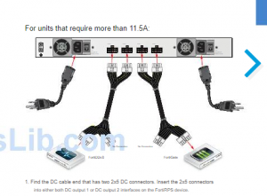
For those of you that have never seen one in the wild before, this is a FortiRPS (it’s the white box closest to us with the black and yellow cables coming out of it). It connects to the FortiGates and does exactly what you think a Forti Redundant Power Supply does……

One thing to note however is that you must cable it differently than the documentation as it is painfully wrong. If you cable it up the way the below image says……losing a power supply will cause you to lose a device. Not so redundant in that configuration eh? Look below, it tells you to put device one on ports 1 and 2 of the FortiRPS and device two on RPS ports 3 and 4. Ports 1 and 2 on the dang thing only goes to a single power supply. In order to actually have your device cabled for REDUNDANT POWER you need to switch the middle cables. IE, plug device one into RPS ports 1 and 3 and device two into RPS ports 2 and 4.
Update FortiGate firmware
Updating or upgrading a firewall is similar to upgrading the operating system so you should make the same preparations. Make sure everything is backed up and you have a plan in case something doesn’t work. Make a checklist to confirm that the update is successful. Finally, ensure you have enough time to do the update.
This is a summary of the steps for updating FortiGate firmware:
Do a full configuration backup using the CLI. This should already be part of your disaster recovery plan. If the upgrade fails, be sure you have a plan to get the firewall back up and running.
This should also be part of your disaster recovery plan. If the upgrade fails, you might be able to switch the active partition. But be prepared for the worst case scenario where you need your old firmware.
This should be part of your plan in a critical failure. In this scenario, this is your plan if your firewall doesn’t come back up after the upgrade. In this case, you need access to the console port to find out why, such as if the DHCP or the IP has changed, or the OS is corrupt. You must have access to the console to find out. If there is no simple fix, be prepared for a format and TFTP reload.
Be sure to read the release notes, preferably more than once. The release notes contain lots of important information, known bugs, fixed bugs, upgrade issues such as lost configuration settings.
For example, double check that your TFTP server is working, your console connection functions properly, you have read the release notes and understand everything that affects the upgrade for your FortiGate models, you have backed up your configuration, you have covered everything you might need for the upgrade.
The upgrade itself usually doesn’t take very long, usually just a few minutes. But make sure you schedule enough time for the entire process and possible contingencies. If the upgrade is successful, you need time to check and confirm that all important functions are working, such as VPNs etc. If the upgrade fails, you need time to sort things out.
Sample upgrade
This is an example of upgrading the FortiGate from FortiOS 6.0.4 to 6.2.0.
To view the FortiOS firmware:
The System Information widget shows the current firmware version.
To check if a new FortiOS firmware version is available:
If a new firmware version is available, a notice appears in the Current version section.
When a new FortiOS version is released, it may not be listed on your FortiGate right away. You can download the firmware from Fortinet Support, then use Upload Firmware to upgrade your FortiGate.
To upgrade to the latest version from FortiGuard:
If you see a message saying there is no valid upgrade path for this firmware version, click All available and select a suitable firmware version for your FortiGate.
Release Notes are also available from the Fortinet Documentation Library.
To upgrade to the latest version from local PC:
FortiGate uploads and installs the firmware, and then restarts and displays the login screen.
See the procedure above to view the FortiOS firmware to ensure you are running the new firmware version.
Interface
Interface settings
Administrator can configure both physical and virtual FortiGate interfaces in Network > Interfaces. There are different options for configuring interfaces when FortiGate is in NAT mode or transparent mode.
To configure an interface in the GUI:
| Interface
Name |
Physical interface names cannot be changed. | |
| Alias | Enter an alternate name for a physical interface on the FortiGate unit. This field appears when you edit an existing physical interface. The alias does not appear in logs.
The maximum length of the alias is 25 characters. |
|
| Link Status | Indicates whether the interface is connected to a network or not (link status is up or down). This field appears when you edit an existing physical interface. | |
| Interface | This field appears when Type is set to VLAN.
Select the name of the physical interface that you want to add a VLAN interface to. Once created, the VLAN interface is listed below its physical interface in the Interface list. You cannot change the physical interface of a VLAN interface except when you add a new VLAN interface. |
|
| Virtual
Domain |
Select the virtual domain to add the interface to.
Administrator accounts with the super_admin profile can change the Virtual Domain. |
|
| Interface
Members |
This section can have two different formats depending on the interface type:
Software Switch: This section is a display-only field showing the interfaces that belong to the virtual interface of the software switch. 802.3ad Aggregate orRedundant Interface: This section includes the available interface list and the selected interface list. |
|
| IP/Netmask | If Addressing Mode is set to Manual, enter an IPv4 address and subnet mask for the interface. FortiGate interfaces cannot have IP addresses on the same subnet. | |
| IPv6 Address | If Addressing Mode is set to Manual and IPv6 support is enabled, enter an IPv6 address and subnet mask for the interface. A single interface can have an IPv4 address, IPv6 address, or both. | |
| Secondary IP Address | Add additional IPv4 addresses to this interface. | |
To configure an interface in the CLI:
config system interface
edit “<Interface_Name>”
set vdom “<VDOM_Name>” set mode static/dhcp/pppoe set ip <IP_address> <netmask> set allowaccess ping https ssh http telnet
set secondary-IP enable config secondaryip
edit 1
set ip 9.1.1.2 255.255.255.0 set allowaccess ping https ssh snmp http telnet
next
end
next end
Configure administrative access to interfaces
You can configure the protocols that administrators can use to access interfaces on the FortiGate. This helps secure access to the FortiGate by restricting access to a limited number of protocols. It helps prevent users from accessing interfaces that you don’t want them to access, such as public-facing ports.
As a best practice, you should configure administrative access when you’re setting the IP address for a port.
To configure administrative access to interfaces in the GUI:
| HTTPS | Allow secure HTTPS connections to the FortiGate GUI through this interface. If configured, this option is enabled automatically. |
| PING | The interface responds to pings. Use this setting to verify your installation and for testing. |
| HTTP | Allow HTTP connections to the FortiGate GUI through this interface. If configured, this option also enables the HTTPS option. |
| SSH | Allow SSH connections to the CLI through this interface. |
| SNMP | Allow a remote SNMP manager to request SNMP information by connecting to this interface. |
| FMG-Access | Allow FortiManager authorization automatically during the communication exchanges between FortiManager and FortiGate devices. |
| CAPWAP | Allow the FortiGate wireless controller to manage a wireless access point such as a FortiAP device. |
Aggregation and redundancy
Link aggregation (IEEE 802.3ad) enables you to bind two or more physical interfaces together to form an aggregated (combined) link. This new link has the bandwidth of all the links combined. If a link in the group fails, traffic is transferred automatically to the remaining interfaces. The only noticeable effect is reduced bandwidth.
This feature is similar to redundant interfaces. The major difference is a redundant interface group only uses one link at a time, where an aggregate link group uses the total bandwidth of the functioning links in the group, up to eight (or more).
Some models support the IEEE standard 802.3ad for link aggregation.
An interface is available to be an aggregate interface if:
l It is a physical interface and not a VLAN interface or subinterface. l It is not already part of an aggregate or redundant interface. l It is in the same VDOM as the aggregated interface. Aggregate ports cannot span multiple VDOMs. l It does not have an IP address and is not configured for DHCP or PPPoE. l It is not referenced in any security policy, VIP, IP Pool, or multicast policy. l It is not an HA heartbeat interface. l It is not one of the FortiGate-5000 series backplane interfaces.
When an interface is included in an aggregate interface, it is not listed on the Network > Interfaces page. Interfaces still appear in the CLI although configuration for those interfaces do not take affect. You cannot configure the interface individually and it is not available for inclusion in security policies, VIPs, IP pools, or routing.
Sample configuration
This example creates an aggregate interface on a FortiGate-140D POE using ports 3-5 with an internal IP address of 10.1.1.123, as well as the administrative access to HTTPS and SSH.
To create an aggregate interface using the GUI:
To create an aggregate interface using the CLI:
FG140P3G15800330 (aggregate) # show config system interface edit “aggregate” set vdom “root”
set ip 10.1.1.123 255.255.255.0
set allowaccess ping https ssh snmp http fgfm radius-acct capwap ftm set type aggregate set member “port3” “port4” “port5” set device-identification enable set lldp-transmission enable set fortiheartbeat enable
set role lan set snmp-index 45
next
end
Redundancy
In a redundant interface, traffic only goes over one interface at any time. This differs from an aggregated interface where traffic goes over all interfaces for increased bandwidth. This difference means redundant interfaces can have more robust configurations with fewer possible points of failure. This is important in a fully-meshed HA configuration.
An interface is available to be in a redundant interface if:
When an interface is included in a redundant interface, it is not listed on the Network > Interfaces page. You cannot configure the interface individually and it is not available for inclusion in security policies, VIPs, or routing.
Sample configuration
To create a redundant interface using the GUI:
To create a redundant interface using the CLI:
config system interface edit “red” set vdom “root”
set ip 10.13.101.100 255.255.255.0 set allowaccess https http set type redundant set member “port4” “port5” “port6” set device-identification enable
set role lan set snmp-index 9
next
end
VLANs
Virtual Local Area Networks (VLANs) multiply the capabilities of your FortiGate unit and can also provide added network security. VLANs use ID tags to logically separate devices on a network into smaller broadcast domains. These smaller domains forward packets only to devices that are part of that VLAN domain. This reduces traffic and increases network security.
VLANs in NAT mode
In NAT mode, the FortiGate unit functions as a layer-3 device. In this mode, the FortiGate unit controls the flow of packets between VLANs and can also remove VLAN tags from incoming VLAN packets. The FortiGate unit can also forward untagged packets to other networks such as the Internet.
In NAT mode, the FortiGate unit supports VLAN trunk links with IEEE 802.1Q-compliant switches or routers. The trunk link transports VLAN-tagged packets between physical subnets or networks. When you add VLAN subinterfaces to the FortiGate’s physical interfaces, the VLANs have IDs that match the VLAN IDs of packets on the trunk link. The FortiGate unit directs packets with VLAN IDs to subinterfaces with matching IDs.
You can define VLAN subinterfaces on all FortiGate physical interfaces. However, if multiple virtual domains are configured on the FortiGate unit, you only have access to the physical interfaces on your virtual domain. The FortiGate unit can tag packets leaving on a VLAN subinterface. It can also remove VLAN tags from incoming packets and add a different VLAN tag to outgoing packets.
Normally in VLAN configurations, the FortiGate unit’s internal interface is connected to a VLAN trunk, and the external interface connects to an Internet router that is not configured for VLANs. In this configuration, the FortiGate unit can apply different policies for traffic on each VLAN interface connected to the internal interface, which results in less network traffic and better security.
Sample topology
In this example, two different internal VLAN networks share one interface on the FortiGate unit and share the connection to the Internet. This example shows that two networks can have separate traffic streams while sharing a single interface. This configuration can apply to two departments in a single company or to different companies.
There are two different internal network VLANs in this example. VLAN_100 is on the 10.1.1.0/255.255.255.0 subnet, and VLAN_200 is on the 10.1.2.0/255.255.255.0 subnet. These VLANs are connected to the VLAN switch.
The FortiGate internal interface connects to the VLAN switch through an 802.1Q trunk. The internal interface has an IP address of 192.168.110.126 and is configured with two VLAN subinterfaces (VLAN_100 and VLAN_200). The external interface has an IP address of 172.16.21.2 and connects to the Internet. The external interface has no VLAN subinterfaces.
When the VLAN switch receives packets from VLAN_100 and VLAN_200, it applies VLAN ID tags and forwards the packets of each VLAN both to local ports and to the FortiGate unit across the trunk link. The FortiGate unit has policies that allow traffic to flow between the VLANs, and from the VLANs to the external network.
Sample configuration
In this example, both the FortiGate unit and the Cisco 2950 switch are installed and connected and basic configuration has been completed. On the switch, you need access to the CLI to enter commands. No VDOMs are enabled in this example.
General configuration steps include:
l the VLAN networks to access each other. l the VLAN networks to access the external network.
To configure the external interface:
config system interface edit external set mode static set ip 172.16.21.2 255.255.255.0
end
To add VLAN subinterfaces:
config system interface edit VLAN_100 set vdom root set interface internal set type vlan set vlanid 100 set mode static set ip 10.1.1.1 255.255.255.0 set allowaccess https ping telnet
next edit VLAN_200 set vdom root set interface internal set type vlan set vlanid 200 set mode static set ip 10.1.2.1 255.255.255.0 set allowaccess https ping telnet
end
To add the firewall addresses:
config firewall address edit VLAN_100_Net set type ipmask set subnet 10.1.1.0 255.255.255.0
next edit VLAN_200_Net set type ipmask set subnet 10.1.2.0 255.255.255.0
end
To add security policies:
Policies 1 and 2 do not need NAT enabled, but policies 3 and 4 do need NAT enabled.
config firewall policy edit 1 set srcintf VLAN_100 set srcaddr VLAN_100_Net set dstintf VLAN_200
set dstaddr VLAN_200_Net set schedule always set service ALL set action accept set nat disable set status enable
next edit 2 set srcintf VLAN_200
set srcaddr VLAN_200_Net set dstintf VLAN_100 set dstaddr VLAN_100_Net set schedule always set service ALL set action accept set nat disable set status enable
next edit 3 set srcintf VLAN_100 set srcaddr VLAN_100_Net set dstintf external set dstaddr all set schedule always set service ALL set action accept set nat enable set status enable
next edit 4 set srcintf VLAN_200 set srcaddr VLAN_200_Net set dstintf external set dstaddr all set schedule always set service ALL set action accept set nat enable set status enable
end
VLANs in transparent mode
In transparent mode, the FortiGate unit behaves like a layer-2 bridge but can still provide services such as antivirus scanning, web filtering, spam filtering, and intrusion protection to traffic. Some limitations of transparent mode is that you cannot use SSL VPN, PPTP/L2TP VPN, DHCP server, or easily perform NAT on traffic. The limits in transparent mode apply to IEEE 802.1Q VLAN trunks passing through the unit.
You can insert the FortiGate unit operating in transparent mode into the VLAN trunk without making changes to your network. In a typical configuration, the FortiGate unit internal interface accepts VLAN packets on a VLAN trunk from a VLAN switch or router connected to internal network VLANs. The FortiGate external interface forwards VLAN-tagged packets through another VLAN trunk to an external VLAN switch or router and on to external networks such as the Internet. You can configure the unit to apply different policies for traffic on each VLAN in the trunk.
To pass VLAN traffic through the FortiGate unit, you add two VLAN subinterfaces with the same VLAN ID, one to the internal interface and the other to the external interface. You then create a security policy to permit packets to flow from the internal VLAN interface to the external VLAN interface. If required, create another security policy to permit packets to flow from the external VLAN interface to the internal VLAN interface. Typically in transparent mode, you do not permit packets to move between different VLANs. Network protection features such as spam filtering, web filtering, and antivirus scanning, are applied through the UTM profiles specified in each security policy, enabling very detailed control over traffic.
When the FortiGate unit receives a VLAN-tagged packet on a physical interface, it directs the packet to the VLAN subinterface with the matching VLAN ID. The VLAN tag is removed from the packet and the FortiGate unit then applies security policies using the same method it uses for non-VLAN packets. If the packet exits the FortiGate unit through a VLAN subinterface, the VLAN ID for that subinterface is added to the packet and the packet is sent to the corresponding physical interface.
Sample topology
In this example, the FortiGate unit is operating in transparent mode and is configured with two VLANs: one with an ID of 100 and the other with ID 200. The internal and external physical interfaces each have two VLAN subinterfaces, one for VLAN_100 and one for VLAN_200.
The IP range for the internal VLAN_100 network is 10.100.0.0/255.255.0.0, and for the internal VLAN_200 network is 10.200.0.0/255.255.0.0.
The internal networks are connected to a Cisco 2950 VLAN switch which combines traffic from the two VLANs onto one in the FortiGate unit’s internal interface. The VLAN traffic leaves the FortiGate unit on the external network interface, goes on to the VLAN switch, and on to the Internet. When the FortiGate units receives a tagged packet, it directs it from the incoming VLAN subinterface to the outgoing VLAN subinterface for that VLAN.
In this example, we create a VLAN subinterface on the internal interface and another one on the external interface, both with the same VLAN ID. Then we create security policies that allow packets to travel between the VLAN_100_int interface and the VLAN_100_ext interface. Two policies are required: one for each direction of traffic. The same is required between the VLAN_200_int interface and the VLAN_200_ext interface, for a total of four security policies.
Sample configuration
There are two main steps to configure your FortiGate unit to work with VLANs in transparent mode:
You can also configure the protection profiles that manage antivirus scanning, web filtering, and spam filtering.
To add VLAN subinterfaces:
config system interface edit VLAN_100_int set type vlan set interface internal set vlanid 100
next edit VLAN_100_ext set type vlan set interface external set vlanid 100
next edit VLAN_200_int set type vlan set interface internal set vlanid 200
next edit VLAN_200_ext set type vlan set interface external set vlanid 200
end To add security policies:
config firewall policy
edit 1
set srcintf VLAN_100_int set srcaddr all set dstintf VLAN_100_ext set dstaddr all set action accept set schedule always set service ALL
next edit 2
set srcintf VLAN_100_ext set srcaddr all set dstintf VLAN_100_int set dstaddr all set action accept set schedule always set service ALL
next edit 3
set srcintf VLAN_200_int set srcaddr all set dstintf VLAN_200_ext set dstaddr all set action accept set schedule always set service ALL
next edit 4
set srcintf VLAN_200_ext
set srcaddr all set dstintf VLAN_200_int set dstaddr all set action accept set schedule always set service ALL
end
Enhanced MAC VLANs
The Media Access Control (MAC) Virtual Local Area Network (VLAN) feature in Linux allows you to configure multiple virtual interfaces with different MAC addresses (and therefore different IP addresses) on a physical interface.
FortiGate implements an enhanced MAC VLAN consisting of a MAC VLAN with bridge functionality. Because each MAC VLAN has a unique MAC address, virtual IP addresses (VIPs) and IP pools are supported, and you can disable Source Network Address Translation (SNAT) in policies.
MAC VLAN cannot be used in a Transparent mode virtual domain (VDOM). In a Transparent mode VDOM, a packet leaves an interface with the MAC address of the original source instead of the interface’s MAC address. FortiGate implements an enhanced version of MAC VLAN where it adds a MAC table in the MAC VLAN which learns the MAC addresses when traffic passes through.
If you configure a VLAN ID for an enhanced MAC VLAN, it won’t join the switch of the underlying interface. When a packet is sent to this interface, a VLAN tag is inserted in the packet and the packet is sent to the driver of the underlying interface. When the underlying interface receives a packet, if the VLAN ID doesn’t match, it won’t deliver the packet to this enhanced MAC VLAN interface.
If you use an interface in an enhanced MAC VLAN, do not use it for other purposes such as a management interface, HA heartbeat interface, or in Transparent VDOMs.
If a physical interface is used by an EMAC VLAN interface, you cannot use it in a Virtual Wire Pair.
In high availability (HA) configurations, enhanced MAC VLAN is treated as a physical interface. It’s assigned a unique physical interface ID and the MAC table is synchronized with the slaves in the same HA cluster.
Example 1: Enhanced MAC VLAN configuration for multiple VDOMs that use the same interface or VLAN
In this example, a FortiGate is connected, through port 1 to a router that’s connected to the Internet. Three VDOMs share the same interface (port 1) which connects to the same router that’s connected to the Internet. Three enhanced MAC VLAN interfaces are configured on port 1 for the three VDOMs. The enhanced MAC VLAN interfaces are in the same IP subnet segment and each have unique MAC addresses.
The underlying interface (port 1) can be a physical interface, an aggregate interface, or a VLAN interface on a physical or aggregate interface.
To configure enhanced MAC VLAN for this example in the CLI:
config system interface edit port1.emacvlan1 set vdom VDOM1 set type emac-vlan set interface port1
next
edit port 1.emacvlan2 set vdom VDOM2 set type emac-vlan set interface port1
next
edit port1.emacvlan3 set vdom VDOM3 set type emac-vlan set interface port1
next
end
Example 2: Enhanced MAC VLAN configuration for shared VDOM links among multiple VDOMs
In this example, multiple VDOMs can connect to each other using enhanced MAC VLAN on network processing unit (NPU) virtual link (Vlink) interfaces.
FortiGate VDOM links (NPU-Vlink) are designed to be peer-to-peer connections and VLAN interfaces on NPU Vlink ports use the same MAC address. Connecting more than two VDOMs using NPU Vlinks and VLAN interfaces is not recommended.
To configure enhanced MAC VLAN for this example in the CLI:
config system interface edit npu0_vlink0.emacvlan1 set vdom VDOM1 set type emac-vlan set interface npu0_vlink0
next
edit npu0_vlink0.emacvlan2 set vdom VDOM3 set type emac-vlan set interface npu0_vlink0
next
edit npu0_vlink1.emacvlan1 set vdom VDOM2 set type emac-vlan set interface npu0_vlink1
next
end
Example 3: Enhanced MAC VLAN configuration for unique MAC addresses for each VLAN interface on the same physical port
Some networks require a unique MAC address for each VLAN interface when the VLAN interfaces share the same physical port. In this case, the enhanced MAC VLAN interface is used the same way as normal VLAN interfaces.
To configure this, use the set vlanid command for the VLAN tag.
To configure enhanced MAC VLAN for this example in the CLI:
config system interface edit interface-name set type emac-vlan set vlanid <VLAN-ID>
set interface <physical-interface>
end
Inter-VDOM routing
In the past, virtual domains (VDOMs) were separate from each other and there was no internal communication. Any communication between VDOMs involved traffic leaving on a physical interface belonging to one VDOM and re-entering the FortiGate unit on another physical interface belonging to another VDOM to be inspected by firewall policies in both directions.
Inter-VDOM routing changes this. With VDOM links, VDOMs can communicate internally without using additional physical interfaces.
Inter-VDOM routing is the communication between VDOMs. VDOM links are virtual interfaces that connect VDOMs. A VDOM link contains a pair of interfaces, each one connected to a VDOM and forming either end of the inter-VDOM connection.
When VDOMs are configured on your FortiGate unit, configuring inter-VDOM routing and VDOM-links is very much like creating a VLAN interface. VDOM-links are managed through the web-based manager or CLI. In the web-based manager, VDOM link interfaces are managed in the network interface list.
To configure a VDOM link in the GUI:
To configure a VDOM link in the CLI:
config system vdom-link edit “<vdom-link-name>” next
end
config system interface edit “<vdom-link-name0>” set vdom “<VDOM Name>” set type vdom-link
next
end
config system interface edit “<vdom-link-name1>” set vdom “<VDOM Name>” set type vdom-link
next
end
To delete a VDOM link in the GUI:
To delete a VDOM link in the CLI:
config system vdom-link delete <VDOM-LINK-Name>
end
Sample configuration: Inter-VDOM routing
This example shows how to configure a FortiGate unit to use inter-VDOM routing.
Two departments of a company, Accounting and Sales, are connected to one FortiGate. The company uses a single ISP to connect to the Internet.
This example includes the following general steps. We recommend following the steps in the order below.
Create the VDOMs
To enable VDOMs and create the Sales and Accounting VDOMs:
config system global set vdom-mode multi-vdom
end
config system vdom edit Accounting
next edit Sales
next end
Configure the physical interfaces
Next, configure the physical interfaces. This example uses three interfaces on the FortiGate unit: port2 (internal), port3 (DMZ), and port1 (external). Port2 and port3 interfaces each have a department’s network connected. Port1 is for all traffic to and from the Internet and uses DHCP to configure its IP address, which is common with many ISPs.
config global config system interface edit port2 set alias AccountingLocal set vdom Accounting set mode static set ip 172.100.1.1 255.255.0.0 set allowaccess https ping ssh
set description “The accounting dept internal interface”
next edit port3 set alias SalesLocal set vdom Sales set mode static set ip 192.168.1.1 255.255.0.0 set allowaccess https ping ssh
set description “The sales dept. internal interface”
next edit port1 set alias ManagementExternal
set vdom root set mode DHCP set distance 5 set gwdetect enable set dns-server-override enable set allowaccess https ssh snmp
set description “The systemwide management interface.”
end end
Configure the VDOM links
To complete the connection between each VDOM and the management VDOM, add the two VDOM links. One pair is the Accounting – management link and the other is the Sales – management link.
When configuring inter-VDOM links, you do not have to assign IP addresses to the links unless you are using advanced features such as dynamic routing that require them. Not assigning IP addresses results in faster configuration and more available IP addresses on your networks.
To configure the Accounting and management VDOM link:
config global config system vdom-link edit AccountVlnk
next end
config system interface edit AccountVlnk0 set vdom Accounting set ip 11.11.11.2 255.255.255.0 set allowaccess https ping ssh
set description “Accounting side of the VDOM link“ next edit AccountVlnk1 set vdom root set ip 11.11.11.1 255.255.255.0 set allowaccess https ping ssh
set description “Management side of the VDOM link“
end
end
To configure the Sales and management VDOM link:
config global config system vdom-link edit SalesVlnk
end
config system interface edit SalesVlnk0 set vdom Accounting set ip 12.12.12.2 255.255.255.0 set allowaccess https ping ssh set description “Sales side of the VDOM link”
next edit SalesVlnk1 set vdom root set ip 12.12.12.1 255.255.255.0 set allowaccess https ping ssh
set description “Management side of the VDOM link”
end end
Configure the firewall and Security Profile
With the VDOMs, physical interfaces, and VDOM links configured, the firewall must now be configured to allow the proper traffic. Firewalls are configured per-VDOM, and firewall objects and routes must be created for each VDOM separately.
To configure the firewall policies from AccountingLocal to Internet:
config vdom edit Accounting config firewall policy edit 1 set name “Accounting-Local-to-Management”
set srcintf port2 set dstintf AccountVlnk set srcaddr all set dstaddr all set action accept set schedule always set service ALL set nat enable
end
end config vdom edit root config firewall policy edit 2 set name “Accounting-VDOM-to-Internet” set srcintf AccountVlnk set dstintf port1 set srcaddr all set dstaddr all set action accept set schedule always set service ALL set nat enable
end
end
To configure the firewall policies from SalesLocal to the Internet:
config vdom edit root config firewall policy edit 6 set name “Sales-local-to-Management”
set srcintf port2 set srcaddr all set dstintf SalesVlnk set dstaddr all set schedule always set service ALL set action accept set logtraffic enable
end
end config vdom edit Sales config firewall policy edit 7 set name “Sales-VDOM-to-Internet” set srcintf SalesVlnk set srcaddr SalesManagement set dstintf external set dstaddr all set schedule always set service OfficeServices set action accept set logtraffic enable end end
Test the configuration
When the inter-VDOM routing has been configured, test the configuration to confirm proper operation.
Testing connectivity ensures that physical networking connections, FortiGate unit interface configurations, and firewall policies are properly configured.
The easiest way to test connectivity is to use the ping and traceroute command to confirm the connectivity of different routes on the network.
Test both from AccountingLocal to Internet and from SalesLocal to Internet.
Software switch
A software switch, or soft switch, is a virtual switch that is implemented at the software or firmware level and not at the hardware level. A software switch can be used to simplify communication between devices connected to different FortiGate interfaces. For example, using a software switch, you can place the FortiGate interface connected to an internal network on the same subnet as your wireless interfaces. Then devices on the internal network can communicate with devices on the wireless network without any additional configuration on the FortiGate unit, such as additional security policies.
A software switch can also be useful if you require more hardware ports for the switch on a FortiGate unit. For example, if your FortiGate unit has a 4-port switch, WAN1, WAN2, and DMZ interfaces, and you need one more port, you can create a soft switch that can include the four-port switch and the DMZ interface, all on the same subnet. These types of applications also apply to wireless interfaces, virtual wireless interfaces, and physical interfaces such as those in FortiWiFi and FortiAP units.
Similar to a hardware switch, a software switch functions like a single interface. A soft switch has one IP address and all the interfaces in the software switch are on the same subnet. Traffic between devices connected to each interface are not regulated by security policies, and traffic passing in and out of the switch are controlled by the same policy.
When setting up a software switch, consider the following:
To create a software switch in the GUI:
To create a software switch in the CLI:
config system switch-interface edit <switch-name> set type switch set member <interface_list>
end
config system interface edit <switch_name> set ip <ip_address> set allowaccess https ssh ping
end
Sample configuration: software switch
For this example, the wireless interface (WiFi) needs to be on the same subnet as the DMZ1 interface to facilitate wireless syncing from an iPhone and a local computer. Because synching between two subnets is problematic, putting both interfaces on the same subnet the synching will work. The software switch will accomplish this.
Merge the WiFi port and DMZ1 port to create a software switch named synchro with an IP address of 10.10.21.12.
Use the following CLI commands to create the switch, add the IP, and then set the administrative access for HTTPS, SSH and Ping.
config system switch-interface edit synchro set type switch set member dmz1 wifi
end
config system interface edit synchro set ip 10.10.21.12 set allowaccess https ssh ping
end
When the soft switch is set up, you now add security policies, DHCP servers, and any other configuration you normally do to configure interfaces on the FortiGate unit.
Zone
Zones are a group of one or more physical or virtual FortiGate interfaces that you can apply security policies to control inbound and outbound traffic. Grouping interfaces and VLAN subinterfaces into zones simplifies the creation of security policies where a number of network segments can use the same policy settings and protection profiles.
When you add a zone, you select the names of the interfaces and VLAN subinterfaces to add to the zone. Each interface still has its own address. Routing is still done between interfaces, that is, routing is not affected by zones. You can use security policies to control the flow of intra-zone traffic.
For example, in the sample configuration below, the network includes three separate groups of users representing different entities on the company network. While each group has its own set of ports and VLANs in each area, they can all use the same security policy and protection profiles to access the Internet. Rather than the administrator making nine separate security policies, he can make administration simpler by adding the required interfaces to a zone and creating three policies.
Sample configuration
You can configure policies for connections to and from a zone but not between interfaces in a zone. For this example, you can create a security policy to go between zone 1 and zone 3, but not between WAN2 and WAN1, or WAN1 and DMZ1.
To create a zone in the GUI:
To configure a zone to include the internal interface and a VLAN using the CLI:
config system zone edit Zone_1 set interface internal VLAN_1 set intrazone deny/allow
end
Using zone in a firewall policy
To configure a firewall policy to allow any interface to access the Internet using the CLI:
config firewall policy edit 2 set name “2” set srcintf “Zone_1” set dstintf “port15” set srcaddr “all” set dstaddr “all” set action accept set schedule “always” set service “ALL” set nat enable
next
end
Intra-zone traffic
In the zone configuration you can set intrazone deny to prohibit the different interfaces in the same zone to talk to each other.
For example, if you have ten interfaces in your zone and the intrazone setting is deny. You now want to allow traffic between a very small number of networks on different interfaces that are part of the zone but you do not want to disable the intra-zone blocking.
In this example, the zone VLANs are defined as: 192.168.1.0/24, 192.168.2.0/24, … 192.168.10.0/24.
This policy allows traffic from 192.168.1.x to 192.168.2.x even though they are in the same zone and intra-zone blocking is enabled. The intra-zone blocking acts as a default deny rule and you have to specifically override it by creating a policy within the zone.
To enable intra-zone traffic, create the following policy:
| Source Interface | Zone-name, e.g., Vlans |
| Source Address | 192.168.1.0/24 |
| Destination | Zone-name (same as Source Interface, i.e., Vlans) |
| Destination Address | 192.168.2.0/24 |
Virtual Wire Pair
A virtual wire pair consists of two interfaces that do not have IP addressing and are treated like a transparent mode VDOM. All traffic received by one interface in the virtual wire pair can only be forwarded to the other interface, provided a virtual wire pair firewall policy allows this traffic. Traffic from other interfaces cannot be routed to the interfaces in a virtual wire pair.
Virtual wire pairs are useful for a typical topology where MAC addresses do not behave normally. For example, port pairing can be used in a Direct Server Return (DSR) topology where the response MAC address pair may not match the request’s MAC address pair.
Sample topology
In this example, a virtual wire pair (port3 and port4) makes it easier to protect a web server that is behind a FortiGate operating as an Internal Segmentation Firewall (ISFW). Users on the internal network access the web server through the ISFW over the virtual wire pair.
To add a virtual wire pair using the GUI:
These interfaces cannot be part of a switch, such as the default LAN/internal interface.
To add a virtual wire pair using the CLI:
config system virtual-wire-pair edit “VWP-name”
set member “port3” “port4” set wildcard-vlan enable/disable
next
end
To create a virtual wire pair policy using the GUI:
To create a virtual wire pair policy using the CLI:
config firewall policy edit 1 set name “VWP-Policy” set srcintf “port3” “port4” set dstintf “port3” “port4” set srcaddr “all” set dstaddr “all” set action accept set schedule “always” set service “ALL” set utm-status enable set fsso disable
next
end
Virtual Domains
Virtual Domains (VDOMs) are used to divide a FortiGate into two or more virtual units that function independently. VDOMs can provide separate security policies and, in NAT mode, completely separate configurations for routing and VPN services for each connected network.
There are two VDOM modes:
By default, most FortiGate units support 10 VDOMs, and many FortiGate models support purchasing a license key to increase the maximum number.
Global settings are configured outside of a VDOM. They effect the entire FortiGate, and include settings such as interfaces, firmware, DNS, some logging and sandboxing options, and others. Global settings should only be changed by top level administrators.
Switching VDOM modes
| Current VDOM mode | New VDOM mode | Rule |
| No VDOM | Split-task VDOM | Allowed |
| Split-task VDOM | No VDOM | Allowed |
| No VDOM | Multi VDOM | Allowed only if CSF is disabled |
| Multi VDOM | No VDOM | Allowed |
| Split-task VDOM | Multi VDOM | Allowed only if CSF is disabled |
| Multi VDOM | Split-task VDOM | Not Allowed. User must first switch to No
VDOM |
Split-task VDOM mode
In split-task VDOM mode, the FortiGate has two VDOMs: the management VDOM (root) and the traffic VDOM (FGtraffic).
The management VDOM is used to manage the FortiGate, and cannot be used to process traffic.
The following GUI sections are available when in the management VDOM:
The traffic VDOM provides separate security policies, and is used to process all network traffic.
The following GUI sections are available when in the traffic VDOM:
(SSO/Identity connectors only) l FortiView l Interface configuration l Packet capture
Split-task VDOM mode is not available on all FortiGate models. The Fortinet Security Fabric supports split-task VDOM mode.
Enable split-task VDOM mode
Split-task VDOM mode can be enabled in the GUI or CLI. Enabling it does not require a reboot, but does log you out of the FortiGate.
When split-task VDOM mode is enabled, all current management configuration is assigned to the root VDOM, and all non-management settings, such as firewall policies and security profiles, are deleted.
To enable split-task VDOM mode in the GUI:
To enable split-task VDOM mode with the CLI:
config system global set vdom-mode split-vdom
end
Assign interfaces to a VDOM
An interface can only be assigned to one of the VDOMs. When split-task VDOM mode is enabled, all interfaces are assigned to the root VDOM. To use an interface in a policy, it must first be assigned to the traffic VDOM.
An interface cannot be moved if it is referenced in an existing configuration.
To assign an interface to a VDOM in the GUI:
To assign an interface to a VDOM using the CLI:
config global config system interface edit <interface>
set vdom <VDOM_name>
next
end
end
Create per-VDOM administrators
Per-VDOM administrators can be created that can access only the management or traffic VDOM. These administrators must use either the prof_admin administrator profile, or a custom profile.
A per-VDOM administrator can only access the FortiGate through a network interface that is assigned to the VDOM that they are assigned to. The interface must also be configured to allow management access. They can also connect to the FortiGate using the console port.
To assign an administrator to multiple VDOMs, they must be created at the global level. When creating an administrator at the VDOM level, the super_admin administrator profile cannot be used.
To create a per-VDOM administrator in the GUI:
To create a per-VDOM administrator using the CLI:
config global config system admin edit <name> set vdom <VDOM_name> set password <password> set accprofile <admin_profile> …
next end
end
Multi VDOM mode
In multi VDOM mode, the FortiGate can have multiple VDOMs that function as independent units. One VDOM is used to manage global settings.
Multi VDOM mode isn’t available on all FortiGate models. The Fortinet Security Fabric does not support multi VDOM mode.
There are three main configuration types in multi VDOM mode:
Independent VDOMs:
Multiple, completely separate VDOMs are created. Any VDOM can be the management VDOM, as long as it has Internet access. There are no inter-VDOM links, and each VDOM is independently managed.
Management VDOM:
A management VDOM is located between the other VDOMs and the Internet, and the other VDOMs connect to the management VDOM with inter-VDOM links. The management VDOM has complete control over Internet access, including the types of traffic that are allowed in both directions. This can improve security, as there is only one point of ingress and egress.
There is no communication between the other VDOMs.
Meshed VDOMs:
VDOMs can communicate with inter-VDOM links. In full-mesh configurations, all the VDOMs are interconnected. In partial-mesh configurations, only some of the VDOMs are interconnected.
In this configuration, proper security must be achieved by using firewall policies and ensuring secure account access for administrators and users.
Multi VDOM configuration examples
The following examples show how to configure per-VDOM settings, such as operation mode, routing, and security policies, in a network that includes the following VDOMs:
l VDOM-A: allows the internal network to access the Internet. l VDOM-B: allows external connections to an FTP server. l root: the management VDOM.
You can use VDOMs in either NAT or transparent mode on the same FortiGate. By default, VDOMs operate in NAT mode.
For both examples, multi VDOM mode must be enabled, and VDOM-A and VDOM-B must be created.
Enable multi VDOM mode
Multi VDOM mode can be enabled in the GUI or CLI. Enabling it does not require a reboot, but does log you out of the device. The current configuration is assigned to the root VDOM.
To enable multi VDOM mode in the GUI:
To enable multi VDOM mode with the CLI:
config system global set vdom-mode multi-vdom
end
Create the VDOMs
To create the VDOMs in the GUI:
To create the VDOMs with the CLI:
config vdom edit <VDOM-A> next
edit <VDOM-B> next
end
end
NAT mode
In this example, both VDOM-A and VDOM-B use NAT mode. A VDOM link is created that allows users on the internal network to access the FTP server.
This configuration requires the following steps:
Configure VDOM-A
VDOM-A allows connections from devices on the internal network to the Internet. WAN 1 and port 1 are assigned to this VDOM.
The per-VDOM configuration for VDOM-A includes the following:
All procedures in this section require you to connect to VDOM-A, either using a global or per-VDOM administrator account.
To add the firewall addresses in the GUI:
| Name | internal-network |
| Type | Subnet |
| Subnet / IP Range | 192.168.10.0/255.255.255.0 |
| Interface | port1 |
| Show in Address List | enabled |
To add the firewall addresses with the CLI:
config vdom edit VDOM-A config firewall address edit internal-network set associated-interface port1 set subnet 192.168.10.0 255.255.255.0
next
end
next
end
To add a default route in the GUI:
| Destination | Subnet |
| IP address | 0.0.0.0/0.0.0.0 |
| Gateway | 172.20.201.7 |
| Interface | wan1 |
| Distance | 10 |
To add a default route with the CLI:
config vdom edit VDOM-A config router static
edit 0
set gateway 172.20.201.7 set device wan1
next
end
next
end
To add the security policy in the GUI:
| Name | VDOM-A-Internet |
| Incoming Interface | port1 |
| Outgoing Interface | wan1 |
| Source Address | internal-network |
| Destination Address | all |
| Schedule | always |
| Service | ALL |
| Action | ACCEPT |
| NAT | enabled |
To add the security policy with the CLI:
config vdom edit VDOM-A config firewall policy edit 0 set name VDOM-A-Internet set srcintf port1 set dstintf wan1 set srcaddr internal-network
set dstaddr all set action accept set schedule always set service ALL set nat enable
next
end
next
end
Configure VDOM-B
VDOM-B allows external connections to reach an internal FTP server. WAN 2 and port 2 are assigned to this VDOM.
The per-VDOM configuration for VDOM-B includes the following:
All procedures in this section require you to connect to VDOM-B, either using a global or per-VDOM administrator account.
To add the firewall addresses in the GUI:
| Address Name | FTP-server |
| Type | Subnet |
| Subnet / IP Range | 192.168.20.10/32 |
| Interface | port2 |
| Show in Address List | enabled |
To add the firewall addresses with the CLI:
config vdom edit VDOM-B config firewall address edit FTP-server set associated-interface port2 set subnet 192.168.20.10 255.255.255.255
next
end
next
end
To add the virtual IP address in the GUI:
| Name | FTP-server-VIP |
| Interface | wan2 |
| External IP Address/Range | 172.25.177.42 |
| Internal IP Address/Range | 192.168.20.10 |
To add the virtual IP address with the CLI:
config firewall vip edit FTP-server-VIP set extip 172.25.177.42 set extintf wan2 set mappedip 192.168.20.10
next
end
To add a default route in the GUI:
| Destination | Subnet |
| IP address | 0.0.0.0/0.0.0.0 |
| Gateway | 172.20.10.10 |
| Interface | wan2 |
| Distance | 10 |
To add a default route with the CLI:
config vdom
edit VDOM-B config router static edit 0
set device wan2 set gateway 172.20.10.10
next
end
next
end
To add the security policy in the GUI:
| Name | Access-server |
| Incoming Interface | wan2 |
| Outgoing Interface | port2 |
| Source Address | all |
| Destination Address | FTP-server-VIP |
| Schedule | always |
| Service | FTP |
| Action | ACCEPT |
| NAT | enabled |
To add the security policy with the CLI:
config vdom edit VDOM-B config firewall policy edit 0 set name Access-server set srcintf wan2 set dstintf port2 set srcaddr all set dstaddr FTP-server-VIP set action accept set schedule always set service FTP set nat enable
next
end
next
end
Configure the VDOM link
The VDOM link allows connections from VDOM-A to VDOM-B. This allows users on the internal network to access the FTP server through the FortiGate.
The configuration for the VDOM link includes the following:
All procedures in this section require you to connect to the global VDOM using a global administrator account.
To add the VDOM link in the GUI:
| Name | VDOM-link | |
| Interface 0 | ||
| Virtual Domain | VDOM-A | |
| IP/Netmask | 0.0.0.0/0.0.0.0 | |
| Interface 1 | ||
| Virtual Domain | VDOM-B | |
| IP/Netmask | 0.0.0.0/0.0.0.0 | |
To add the VDOM link with the CLI:
config global config system vdom-link edit vlink end
config system interface edit VDOM-link0
set vdom VDOM-A set ip 0.0.0.0 0.0.0.0
next edit VDOM-link1
set vdom VDOM-B set ip 0.0.0.0 0.0.0.0
next end
end
To add the firewall address on VDOM-A in the GUI:
| Address Name | FTP-server |
| Type | Subnet |
| Subnet / IP Range | 192.168.20.10/32 |
| Interface | VDOM-link0 |
| Show in Address List | enabled |
| Static Route Configuration | enabled |
To add the firewall addresses on VDOM-A with the CLI:
config vdom
edit VDOM-B
config firewall address
edit FTP-server
set associated-interface VDOM-link0 set allow-routing enable set subnet 192.168.20.10 255.255.255.255
next
end
next
end
To add the static route on VDOM-A in the GUI:
| Destination | Named Address |
| Named Address | FTP-server |
| Gateway | 0.0.0.0 |
| Interface | VDOM-link0 |
To add the static route on VDOM-A with the CLI:
config vdom
edit VDOM-A config router static
edit 0
set device VDOM-link0 set dstaddr FTP-server
next
end
next
end
To add the security policy on VDOM-A in the GUI:
| Name | Access-FTP-server |
| Incoming Interface | port1 |
| Outgoing Interface | VDOM-link0 |
| Source | internal-network |
| Destination | FTP-server |
| Schedule | always |
| Service | FTP |
| Action | ACCEPT |
| NAT | disabled |
To add the security policy on VDOM-A with the CLI:
config vdom
edit VDOM-A config firewall policy
edit 0
set name Access-FTP-server set srcintf port1 set dstintf VDOM-link0 set srcaddr internal-network set dstaddr FTP-server set action accept set schedule always set service FTP
next end next
end
To add the firewall address on VDOM-B in the GUI:
| Address Name | internal-network |
| Type | Subnet |
| Subnet / IP Range | 192.168.10.0/24 |
| Interface | VDOM-link1 |
| Show in Address List | enabled |
| Static Route Configuration | enabled |
To add the firewall addresses on VDOM-B with the CLI:
config vdom
edit VDOM-B
config firewall address
edit internal-network
set associated-interface VDOM-link1 set allow-routing enable set subnet 192.168.10.0 255.255.255.0
next
end
next
end
To add the static route on VDOM-B in the GUI:
| Destination | Named Address |
| Named Address | internal-network |
| Gateway | 0.0.0.0 |
| Interface | VDOM-link1 |
To add the static route on VDOM-B with the CLI:
config vdom
edit VDOM-B config router static
edit 0
set device VDOM-link1
set dstaddr internal-network
next
end
next
end
To add the security policy on VDOM-B in the GUI:
| Name | Internal-server-access |
| Incoming Interface | VDOM-link1 |
| Outgoing Interface | port2 |
| Source | internal-network |
| Destination | FTP-server |
| Schedule | always |
| Service | FTP |
| Action | ACCEPT |
| NAT | disabled |
To add the security policy on VDOM-B with the CLI:
config vdom
edit VDOM-B config firewall policy
edit 0
set name Internal-server-access set srcintf VDOM-link1 set dstintf port2 set srcaddr internal-network set dstaddr FTP-server set action accept set schedule always set service FTP
next
end
next
end
NAT and transparent mode
In this example, VDOM-A uses NAT mode and VDOM-B uses transparent mode.
This configuration requires the following steps:
Configure VDOM-A
VDOM-A allows connections from devices on the internal network to the Internet. WAN 1 and port 1 are assigned to this VDOM.
The per-VDOM configuration for VDOM-A includes the following:
All procedures in this section require you to connect to VDOM-A, either using a global or per-VDOM administrator account.
To add the firewall addresses in the GUI:
| Name | internal-network |
| Type | Subnet |
| Subnet / IP Range | 192.168.10.0/24 |
| Interface | port1 |
| Show in Address List | enabled |
To add the firewall addresses with the CLI:
config vdom edit VDOM-A config firewall address edit internal-network set associated-interface port1 set subnet 192.168.10.0 255.255.255.0
next
end
next
end
To add a default route in the GUI:
| Destination | Subnet | |
| IP address | 0.0.0.0/0.0.0.0 | |
| Gateway | 172.20.201.7 | |
| Interface | wan1 | |
| Distance | 10 |
To add a default route with the CLI:
config vdom
edit VDOM-A config router static
edit 0
set gateway 172.20.201.7 set device wan1
next
end
next
end
To add the security policy in the GUI:
| Name | VDOM-A-Internet |
| Incoming Interface | port1 |
| Outgoing Interface | wan1 |
| Source Address | internal-network |
| Destination Address | all |
| Schedule | always |
| Service | ALL |
| Action | ACCEPT |
| NAT | enabled |
To add the security policy with the CLI:
config vdom
edit VDOM-A config firewall policy
edit 0
set name VDOM-A-Internet set srcintf port1 set dstintf wan1 set srcaddr internal-network set dstaddr all set action accept set schedule always set service ALL set nat enable
next
end
next end
Configure VDOM-B
VDOM-B allows external connections to reach an internal FTP server. WAN 2 and port 2 are assigned to this VDOM.
The per-VDOM configuration for VDOM-B includes the following:
All procedures in this section require you to connect to VDOM-B, either using a global or per-VDOM administrator account.
To add the firewall addresses in the GUI:
| Address Name | FTP-server |
| Type | Subnet |
| Subnet / IP Range | 172.25.177.42/32 |
| Interface | port2 |
| Show in Address List | enabled |
To add the firewall addresses with the CLI:
config vdom edit VDOM-B config firewall address edit FTP-server set associated-interface port2 set subnet 172.25.177.42 255.255.255.255
next
end
next
end
To add a default route in the GUI:
| Destination | Subnet |
| IP address | 0.0.0.0/0.0.0.0 |
| Gateway | 172.20.10.10 |
To add a default route with the CLI:
config vdom edit VDOM-B config router static
edit 0 set gateway 172.20.10.10
next
end next
end
To add the security policy in the GUI:
| Name | Access-server |
| Incoming Interface | wan2 |
| Outgoing Interface | port2 |
| Source Address | all |
| Destination Address | FTP-server |
| Schedule | always |
| Service | FTP |
| Action | ACCEPT |
To add the security policy with the CLI:
config vdom
edit VDOM-B config firewall policy
edit 0
set name Access-server set srcintf wan2 set dstintf port2 set srcaddr all set dstaddr FTP-server-VIP set action accept set schedule always set service FTP
next
end
next
end
Advanced configurations
VDOM
You can use VDOMs (virtual domains) as a method of dividing a FortiGate unit into multiple virtual units. Each unit functions as an independent unit. VDOMs can provide separate security policies and, in NAT mode, completely separate configurations for routing and VPN services for each connected network.
By default, most FortiGate units support up to ten VDOMs. Many FortiGate models support purchasing a license key to increase the maximum number of VDOMs.
Sample topology
In this sample, you use VDOMs to provide Internet access for two different companies (called Company A and Company B) using a single FortiGate.
VDOM mode
There are three VDOM modes:
You can change VDOM modes in the following ways:
To enable VDOMs in the GUI:
On FortiGate 60 series models, you must use CLI to enable VDOMs.
To enable VDOMs in the CLI:
config system global set vdom-mode no-vdom/split-vdom/multi-vdom
end
To add a VDOMs in the GUI:
To add a VDOMs in the CLI:
config vdom edit <new_vdom_name>
end
To edit a VDOMs in the GUI:
To edit a VDOMs in the CLI:
config vdom edit vdom_name config system settings
set opmode nat
end
To delete a VDOMs in the GUI:
To delete a VDOMs in the CLI:
config vdom delete vdom_name
end
Operation mode
A FortiGate can operate in one of two modes: NAT/Route or Transparent.
NAT/Route is the most common operating mode. In this mode, a FortiGate is installed as a gateway or router between two networks. In most cases, it is used between a private network and the Internet. This allows the FortiGate to hide the IP addresses of the private network using network address translation (NAT). You can also use NAT/Route mode when several Internet service providers (ISPs) provide the FortiGate with redundant Internet connections.
In Transparent mode, the FortiGate is installed between the internal network and the router. In this mode, the FortiGate does not changes any IP addresses and only applies security scanning to traffic. When you add a FortiGate to a network in Transparent mode, no network changes are requiredexcept to provide the FortiGate with a management IP address. Transparent mode is used primarily when there is a need to increase network protection but changing the configuration of the network itself is impractical.
By default, new VDOMs are set to NAT/Route operation mode. If you want a VDOM to be in Transparent operation mode, you must manually change it.
To change operation mode in the CLI:
config system settings set opmode nat | transparent
end
SNMP
The Simple Network Management Protocol (SNMP) enables you to monitor hardware on your network. You can configure the hardware, such as the FortiGate SNMP agent, to report system information and send traps (alarms or event messages) to SNMP managers.
SNMP v1/v2c
SNMPWALK is a Simple Network Management Protocol (SNMP) application present on the Security Management
System (SMS) CLI that uses SNMP GETNEXT requests to query a network device for information. An object identifier (OID) may be given on the command line. This OID specifies which portion of the object identifier space will be searched using GETNEXT requests. All variables in the subtree below the given OID are queried and their values presented to the user.
To configure SNMP v1/v2c:
config system snmp community edit 1 set name “REGR-SYS” config hosts edit 1 set ip 10.1.100.11 255.255.255.255
next
end
set events cpu-high mem-low log-full intf-ip vpn-tun-up vpn-tun-down ha-switch ha-hb-
failure ips-signature ips-anomaly av-virus av-oversize av-pattern av-fragmented fm-if-change fm-conf-change bgp-established bgp-backward-transition ha-member-up ha-member-down ent-confchange av-conserve av-bypass av-oversize-passed av-oversize-blocked ips-pkg-update ips-failopen faz-disconnect wc-ap-up wc-ap-down fswctl-session-up fswctl-session-down load-balancereal-server-down device-new next
end
Below is a sample SNMPWALK output on the above configuration:
snmpwalk -v2c -c REGR-SYS 10.1.100.1 1 SNMPv2-MIB::sysDescr.0 = STRING: REGR-SYS
SNMPv2-MIB::sysObjectID.0 = OID: FORTINET-FORTIGATE-MIB::fgt140P
DISMAN-EVENT-MIB::sysUpTimeInstance = Timeticks: (224721) 0:37:27.21
SNMPv2-MIB::sysContact.0 = STRING: Gundam-Justice
SNMPv2-MIB::sysName.0 = STRING: FortiGate-140D-POE
SNMPv2-MIB::sysLocation.0 = STRING: Gundam-Seed
SNMPv2-MIB::sysServices.0 = INTEGER: 78
SNMPv2-MIB::sysORLastChange.0 = Timeticks: (0) 0:00:00.00
SNMPv2-MIB::sysORIndex.1 = INTEGER: 1
SNMPv2-MIB::sysORID.1 = OID: SNMPv2-SMI::zeroDotZero.0 SNMPv2-MIB::sysORDescr.1 = STRING:
SNMPv2-MIB::sysORUpTime.1 = Timeticks: (0) 0:00:00.00
IF-MIB::ifNumber.0 = INTEGER: 45
IF-MIB::ifIndex.1 = INTEGER: 1
IF-MIB::ifIndex.2 = INTEGER: 2
IF-MIB::ifIndex.3 = INTEGER: 3
IF-MIB::ifIndex.4 = INTEGER: 4
IF-MIB::ifIndex.5 = INTEGER: 5
IF-MIB::ifIndex.6 = INTEGER: 6
IF-MIB::ifIndex.7 = INTEGER: 7
IF-MIB::ifIndex.8 = INTEGER: 8
IF-MIB::ifIndex.9 = INTEGER: 9
IF-MIB::ifIndex.10 = INTEGER: 10
IF-MIB::ifIndex.11 = INTEGER: 11
IF-MIB::ifIndex.12 = INTEGER: 12
IF-MIB::ifIndex.13 = INTEGER: 13
IF-MIB::ifIndex.14 = INTEGER: 14
IF-MIB::ifIndex.15 = INTEGER: 15
—————truncated———————–
SNMP v3
Authentication is used to ensure the identity of users. Privacy allows for encryption of SNMP v3 messages to ensure confidentiality of data. These protocols provide a higher level of security than is available in SNMP v1 and v2c, which use community strings for security. Both authentication and privacy are optional.
To configure SNMP v3:
config system snmp user edit “v3user” set notify-hosts 10.1.100.11
set events cpu-high mem-low log-full intf-ip vpn-tun-up vpn-tun-down ha-switch ha-hb-
failure ips-signature ips-anomaly av-virus av-oversize av-pattern av-fragmented fm-if-change fm-conf-change ha-member-up ha-member-down ent-conf-change av-conserve av-bypass av-oversizepassed av-oversize-blocked ips-pkg-update faz-disconnect set security-level auth-priv
set auth-pwd ENC nu9t3vKW5BOw03RBzrp8cRVgq5kXg/ZqMgEACPNeNi+o-
pioCE6ztKXjkn+eReY9DxSUjgO5TckbMgqfH+YpVzNJxvL8jueq8g00Hs5gJyRy-
ueP22xsRudVv6v0gdfX47WTYvhqxBIDGnUKsL4NsztG0rJVUVZWNVPepdtWYMNDgGgePhvir3Rk/M1OjbS+mGX0YkYw== set priv-pwd ENC
YlZKutoqQPWK0fut2QPy-
fFayGaMssCaBT4y+6mP0AXNC+NJSbOeYCfhL4XFvyvhH8l07Hww6QYcoIGAU9jBcMt+tJk97MExQ/VutOwlSizKNqfy9MnJjLWARoKQwOYKpnE2b-
tZGxiFnFmD37mQHcKAtC9n531CPTYOuCtPQB26IjQ97yyWca4SqhRvuSZs6sjkSVWA== next
end
Below is a sample SNMPWALK output on the above configuration:
snmpwalk -v3 -u v3user -c REGR-SYS -a sha -A 1234567890 -x aes -X 1234567890 10.1.100.1 1 -l authpriv
SNMPv2-MIB::sysDescr.0 = STRING: REGR-SYS
SNMPv2-MIB::sysObjectID.0 = OID: FORTINET-FORTIGATE-MIB::fgt140P
DISMAN-EVENT-MIB::sysUpTimeInstance = Timeticks: (14328) 0:02:23.28
SNMPv2-MIB::sysContact.0 = STRING: Gundam-Justice
SNMPv2-MIB::sysName.0 = STRING: FortiGate-140D-POE
SNMPv2-MIB::sysLocation.0 = STRING: Gundam-Seed
SNMPv2-MIB::sysServices.0 = INTEGER: 78
SNMPv2-MIB::sysORLastChange.0 = Timeticks: (0) 0:00:00.00
SNMPv2-MIB::sysORIndex.1 = INTEGER: 1
SNMPv2-MIB::sysORID.1 = OID: SNMPv2-SMI::zeroDotZero.0 SNMPv2-MIB::sysORDescr.1 = STRING:
SNMPv2-MIB::sysORUpTime.1 = Timeticks: (0) 0:00:00.00
IF-MIB::ifNumber.0 = INTEGER: 45
IF-MIB::ifIndex.1 = INTEGER: 1
IF-MIB::ifIndex.2 = INTEGER: 2
IF-MIB::ifIndex.3 = INTEGER: 3
IF-MIB::ifIndex.4 = INTEGER: 4
IF-MIB::ifIndex.5 = INTEGER: 5
IF-MIB::ifIndex.6 = INTEGER: 6
IF-MIB::ifIndex.7 = INTEGER: 7
IF-MIB::ifIndex.8 = INTEGER: 8
IF-MIB::ifIndex.9 = INTEGER: 9
IF-MIB::ifIndex.10 = INTEGER: 10
IF-MIB::ifIndex.11 = INTEGER: 11
IF-MIB::ifIndex.12 = INTEGER: 12
IF-MIB::ifIndex.13 = INTEGER: 13
IF-MIB::ifIndex.14 = INTEGER: 14
IF-MIB::ifIndex.15 = INTEGER: 15
IF-MIB::ifIndex.16 = INTEGER: 16
IF-MIB::ifIndex.17 = INTEGER: 17
IF-MIB::ifIndex.18 = INTEGER: 18
IF-MIB::ifIndex.19 = INTEGER: 19
IF-MIB::ifIndex.20 = INTEGER: 20
IF-MIB::ifIndex.21 = INTEGER: 21
IF-MIB::ifIndex.22 = INTEGER: 22
IF-MIB::ifIndex.23 = INTEGER: 23
IF-MIB::ifIndex.24 = INTEGER: 24
IF-MIB::ifIndex.25 = INTEGER: 25
IF-MIB::ifIndex.26 = INTEGER: 26
IF-MIB::ifIndex.27 = INTEGER: 27
IF-MIB::ifIndex.28 = INTEGER: 28
IF-MIB::ifIndex.29 = INTEGER: 29
IF-MIB::ifIndex.30 = INTEGER: 30
IF-MIB::ifIndex.31 = INTEGER: 31
IF-MIB::ifIndex.32 = INTEGER: 32
IF-MIB::ifIndex.33 = INTEGER: 33
IF-MIB::ifIndex.34 = INTEGER: 34
IF-MIB::ifIndex.35 = INTEGER: 35
IF-MIB::ifIndex.36 = INTEGER: 36
IF-MIB::ifIndex.37 = INTEGER: 37
IF-MIB::ifIndex.38 = INTEGER: 38
IF-MIB::ifIndex.39 = INTEGER: 39
IF-MIB::ifIndex.40 = INTEGER: 40
IF-MIB::ifIndex.41 = INTEGER: 41
IF-MIB::ifIndex.42 = INTEGER: 42
IF-MIB::ifIndex.43 = INTEGER: 43
IF-MIB::ifIndex.44 = INTEGER: 44
IF-MIB::ifIndex.45 = INTEGER: 45
=====================Truncated=========================
Important SNMP traps
Link Down and Link Up traps
This trap is sent when a FortiGate port goes down or is brought up. For example, the below traps are generated when the state of port34 is set to down using set status down and then brought up using set status up.
NET-SNMP version 5.7.3 2019-01-31 14:11:48 10.1.100.1(via UDP: [10.1.100.1]:162->
[10.1.100.11]:162) TRAP, SNMP v1, community REGR-SYS SNMPv2-MIB::snmpTraps Link Down Trap (0) Uptime: 0:14:44.95 IF-MIB::ifIndex.42 = INTEGER: 42 IF-MIB::ifAdminStatus.42 = INTEGER: down (2) IF-MIB::ifOperStatus.42 = INTEGER: down(2) FORTINET-CORE-MIB::fnSysSerial.0 = STRING: FG140P3G15800330 SNMPv2-MIB::sysName.0 = STRING: FortiGate-140D-POE
2019-01-31 14:11:48 <UNKNOWN> [UDP: [10.1.100.1]:162->[10.1.100.11]:162]: DISMAN-EVENTMIB::sysUpTimeInstance = Timeticks: (88495) 0:14:44.95 SNMPv2-MIB::snmpTrapOID.0 = OID: IFMIB::linkDown IF-MIB::ifIndex.42 = INTEGER: 42 IF-MIB::ifAdminStatus.42 = INTEGER: down(2) IFMIB::ifOperStatus.42 = INTEGER: down(2) FORTINET-CORE-MIB::fnSysSerial.0 = STRING:
FG140P3G15800330 SNMPv2-MIB::sysName.0 = STRING: FortiGate-140D-POE 2019-01-31 14:12:01
10.1.100.1(via UDP: [10.1.100.1]:162->[10.1.100.11]:162) TRAP, SNMP v1, community REGR-SYS
SNMPv2-MIB::snmpTraps Link Up Trap (0) Uptime: 0:14:57.98 IF-MIB::ifIndex.42 = INTEGER: 42 IFMIB::ifAdminStatus.42 = INTEGER: up(1) IF-MIB::ifOperStatus.42 = INTEGER: up(1) FORTINET-COREMIB::fnSysSerial.0 = STRING: FG140P3G15800330 SNMPv2-MIB::sysName.0 = STRING: FortiGate-140DPOE
2019-01-31 14:12:01 <UNKNOWN> [UDP: [10.1.100.1]:162->[10.1.100.11]:162]: DISMAN-EVENTMIB::sysUpTimeInstance = Timeticks: (89798) 0:14:57.98 SNMPv2-MIB::snmpTrapOID.0 = OID: IFMIB::linkUp IF-MIB::ifIndex.42 = INTEGER: 42 IF-MIB::ifAdminStatus.42 = INTEGER: up(1) IFMIB::ifOperStatus.42 = INTEGER: up(1) FORTINET-CORE-MIB::fnSysSerial.0 = STRING: FG140P3G15800330 SNMPv2-MIB::sysName.0 = STRING: FortiGate-140D-POE fgFmTrapIfChange trap
This trap is sent when any changes are detected on the interface. The change can be very simple, such as giving an IPV4 address. For example, the user has given the IP address of 1.2.3.4/24 to port 1 and the EMS Manager has detected the below trap.
DISMAN-EXPRESSION-MIB::sysUpTimeInstance = Timeticks: (7975058) 22:09:10.58 SNMPv2-MIB::snmpTrapOID.0 = OID: FORTINET-FORTIGATE-MIB::fgFmTrapIfChange FORTINET-CORE-MIB::fnSysSerial.0 = STRING: FG140P3G15800330 IF-MIB::ifName.45 = STRING: port1 FORTINET-FORTIGATEMIB::fgManIfIp.0 = IpAddress: 1.2.3.4 FORTINET-FORTIGATE-MIB::fgManIfMask.0 = IpAddress:
255.255.255.0 FORTINET-FORTIGATE-MIB::fgManIfIp6.0 = STRING: 0:0:0:0:0:0:0:0 entConfigChange trap
The change to the interface in the example above has also triggered the ConfChange Trap which is sent along with the fgFmTrapIfChange trap.
2018-11-15 09:30:23 FGT_A [UDP: [172.16.200.1]:162->[172.16.200.55]:162]: DISMAN-EXPRESSIONMIB::sysUpTimeInstance = Timeticks: (8035097) 22:19:10.97 SNMPv2-MIB::snmpTrapOID.0 = OID: ENTITY-MIB::entConfigChange fgTrapDeviceNew trap
This trap is triggered when a new device like FortiAP/FortiSwitch is connected to the FortiGate. For example, the below scenario has given the device a new trap for adding FortiAP on a POE interface of FGT140D-POE. The trap has important information about the device name, device MAC address, and when it was last seen.
2018-11-15 11:17:43 UDP/IPv6: [2000:172:16:200::1]:162 [UDP/IPv6: [2000:172:16:200::1]:162]: DISMAN-EXPRESSION-MIB::sysUpTimeInstance = Timeticks: (520817) 1:26:48.17 SNMPv2-MIB::snmpTrapOID.0 = OID: FORTINET-FORTIGATE-MIB::fgTrapDeviceNew FORTINET-CORE-MIB::fnSysSerial.0 = STRING: FG140P3G15800330 SNMPv2-MIB::sysName.0 = STRING: FGT_A IF-MIB::ifIndex.0 = INTEGER: 0
FORTINET-FORTIGATE-MIB::fgVdEntIndex.0 = INTEGER: 0 FORTINET-FORTIGATE-MIB::fgDeviceCreated.0
= Gauge32: 5 FORTINET-FORTIGATE-MIB::fgDeviceLastSeen.0 = Gauge32: 5 FORTINET-FORTIGATEMIB::fgDeviceMacAddress.0 = STRING: 90:6c:ac:f9:97:a0
2018-11-15 11:17:43 FGT_A [UDP: [172.16.200.1]:162->[172.16.200.55]:162]: DISMAN-EXPRESSIONMIB::sysUpTimeInstance = Timeticks: (520817) 1:26:48.17 SNMPv2-MIB::snmpTrapOID.0 = OID:
FORTINET-FORTIGATE-MIB::fgTrapDeviceNew FORTINET-CORE-MIB::fnSysSerial.0 = STRING:
FG140P3G15800330 SNMPv2-MIB::sysName.0 = STRING: FGT_A IF-MIB::ifIndex.0 = INTEGER: 0
FORTINET-FORTIGATE-MIB::fgVdEntIndex.0 = INTEGER: 0 FORTINET-FORTIGATE-MIB::fgDeviceCreated.0
= Gauge32: 5 FORTINET-FORTIGATE-MIB::fgDeviceLastSeen.0 = Gauge32: 5 FORTINET-FORTIGATE-
MIB::fgDeviceMacAddress.0 = STRING: 90:6c:ac:f9:97:a0 fgTrapAvOversize trap
The fgTrapAvOversize trap is generated when Antivirus Scanner detects an Oversized File.
019-01-31 13:22:04 10.1.100.1(via UDP: [10.1.100.1]:162->[10.1.100.11]:162) TRAP, SNMP v1, community REGR-SYS FORTINET-FORTIGATE-MIB::fgt140P Enterprise Specific Trap (602) Uptime: 1 day, 3:41:10.31 FORTINET-CORE-MIB::fnSysSerial.0 = STRING: FG140P3G15800330 SNMPv2-MIB::sysName.0 =
STRING: FortiGate-140D-POE 2019-01-31 13:22:29 <UNKNOWN> [UDP: [10.1.100.1]:162->
[10.1.100.11]:162]: DISMAN-EVENT-MIB::sysUpTimeInstance = Timeticks: (9967031) 1 day,
3:41:10.31 SNMPv2-MIB::snmpTrapOID.0 = OID: FORTINET-FORTIGATE-MIB::fgTrapAvOversize FORTINETCORE-MIB::fnSysSerial.0 = STRING: FG140P3G15800330 SNMPv2-MIB::sysName.0 = STRING: FortiGate-
140D-POE
DHCP server
A DHCP server provides an address from a defined address range to a client on the network, when requested.
You can configure one or more DHCP servers on any FortiGate interface. A DHCP server dynamically assigns IP addresses to hosts on the network connected to the interface. The host computers must be configured to obtain their IP addresses using DHCP.
You can configure a FortiGate interface as a DHCP relay. The interface forwards DHCP requests from DHCP clients to an external DHCP server and returns the responses to the DHCP clients. The DHCP server must have appropriate routing so that its response packets to the DHCP clients arrive at the unit.
Configure DHCP on the FortiGate
To add a DHCP server on the GUI:
To add a DHCP server on the CLI:
config system dhcp server edit 1 set dns-service default set default-gateway 192.168.1.2 set netmask 255.255.255.0 set interface “port1” config ip-range edit 1 set start-ip 192.168.1.1 set end-ip 192.168.1.1
next edit 2 set start-ip 192.168.1.3 set end-ip 192.168.1.254
next
end set timezone-option default set tftp-server “172.16.1.2”
next end
DHCP options
When adding a DHCP server, you can include DHCP codes and options. The DHCP options are BOOTP vendor information fields that provide additional vendor-independent configuration parameters to manage the DHCP server. For example, you might need to configure a FortiGate DHCP server that gives out a separate option as well as an IP address, such as an environment that needs to support PXE boot with Windows images.
The option numbers and codes are specific to the application. The documentation for the application indicates the values to use. Option codes are represented in a option value/HEX value pairs. The option is a value between 1 and 255.
You can add up to three DHCP code/option pairs per DHCP server.
To configure option 252 with value http://192.168.1.1/wpad.dat using the CLI:
config system dhcp server edit <server_entry_number>
set option1 252 687474703a2f2f3139322e3136382e312e312f777061642e646174 end
For detailed information about DHCP options, see RFC 2132, DHCP Options and BOOTP Vendor Extensions.
Option-82
DHCP option 82, also known as the DHCP relay agent information option, helps protect FortiGate against attacks such as spoofing (forging) of IP addresses and MAC addresses, and DHCP IP address starvation.
FG3H1E5818900749 (1) # show config reserved-address edit 1 set type option82 set ip 100.100.100.12 set circuit-id-type hex set circuit-id “00010102” set remote-id-type hex set remote-id “704ca5e477d6”
next
end
| FG3H1E5818900749 (1) # set | |
| type | DHCP reserved-address type. |
| *ip | IP address to be reserved for the MAC address. |
| circuit-id-type | DHCP option type. |
| circuit-id | Option 82 circuit-ID of the client that will get the reserved IP address. |
| remote-id-type | DHCP option type. |
| remote-id | Option 82 remote-ID of the client that will get the reserved IP address. |
| description | Description. |
FortiGate-140D-POE (1) # set type
mac Match with MAC address. option82 Match with DHCP option 82.
FortiGate-140D-POE (1) # set circuit-id-type hex DHCP option in hex. string DHCP option in string.
FortiGate-140D-POE (1) # set remote-id-type hex DHCP option in hex. string DHCP option in string.
Option-42
This option specifies a list of the NTP servers available to the client by IP address.
FortiGate-140D-POE # config system dhcp server
FortiGate-140D-POE (server) # edit 2
FortiGate-140D-POE (2) # set ntp-service local IP address of the interface the DHCP server is added to becomes the client’s NTP server IP address. default Clients are assigned the FortiGate’s configured NTP servers. specify Specify up to 3 NTP servers in the DHCP server configuration.
FortiGate-140D-POE (2) # set ntp-service
FortiGate-140D-POE (2) # set ntp-server1
<class_ip> Class A,B,C ip xxx.xxx.xxx.xxx
FortiGate-140D-POE (2) # set ntp-server1 1.1.1.1
FortiGate-140D-POE (2) # set ntp-server2 2.2.2.2 FortiGate-140D-POE (2) # set ntp-server3 3.3.3.3
FortiGate-140D-POE (2) # end
Use Custom Images for Replacement Messages
The replacement message list in System > Replacement Messages enables you to view and customize replacement messages. Highlight the replacement messages you want to edit and customize the message content to your requirements. Hit Save when done. If you do not see the message you want to edit, select the Extended View option in the upper right-hand corner of the screen.
If you make a mistake, select Restore Default to return to the original message and code base.
Replacement message images
You can add images to replacement messages on:
Adding images to replacement messages
To add images to replacement messages in the GUI:
Modify images in replacement messages
Replacement messages can be modified to include an HTML message or content that suits your organization. A list of common replacement messages appear in the main window. Select Extended View to see the entire list and all categories for replacement messages.
To modify an image in a replacement message:
In the bottom pane of the GUI the message will be displayed on the left alongside the HTML code on the right. The message view changes in real-time as you edit the content.
Replacement message groups
Replacement message groups enable you to view common messages in groups for large carriers. Message groups can be configured by going to Config > Replacement Message Group.
Using the defined groups, you can manage specific replacement messages from a single location, rather than searching through the entire replacement message list.
If you enable virtual domains (VDOMs) on the FortiGate unit, replacement message groups are configured separately for each virtual domain. Each VDOM has its own default replacement message group, configured from System > Replacement Message Group.
When you modify a message in a replacement message group, a reset icon appears beside the message in the group.
Select the reset icon to reset the message in the replacement message group to the default version.
Cluster setup
HA active-passive cluster setup
An HA Active-Passive (A-P) cluster can be set up using the GUI or CLI.
This example uses the following network topology:
To set up an HA A-P cluster using the GUI:
| Mode | Active-Passive |
| Device priority | 128 or higher |
| Group name | Example_cluster |
| Heartbeat interfaces | ha1 and ha2 |
Except for the device priority, these settings must be the same on all FortiGates in the cluster.
The FortiGate negotiates to establish an HA cluster. Connectivity with the FortiGate may be temporarily lost as the HA cluster negotiates and the FGCP changes the MAC addresses of the FortiGate’s interfaces.
To set up an HA A-P cluster using the CLI:
config system global set hostname Example1_host
end
Changing the host name makes it easier to identify individual cluster units in the cluster operations.
config system ha set mode a-p
set group-name Example_cluster
set hbdev ha1 10 ha2 20 end
HA active-active cluster setup
An HA Active-Active (A-A) cluster can be set up using the GUI or CLI.
This example uses the following network topology:
To set up an HA A-A cluster using the GUI:
| Mode | Active-Active |
| Device priority | 128 or higher |
| Group name | Example_cluster |
| Heartbeat interfaces | ha1 and ha2 |
Except for the device priority, these settings must be the same on all FortiGates in the cluster.
The FortiGate negotiates to establish an HA cluster. Connectivity with the FortiGate may be temporarily lost as the HA cluster negotiates and the FGCP changes the MAC addresses of the FortiGate’s interfaces.
To set up an HA A-P cluster using the CLI:
config system global set hostname Example1_host
end
Changing the host name makes it easier to identify individual cluster units in the cluster operations.
config system ha set mode a-a
set group-name Example_cluster
set hbdev ha1 10 ha2 20 end
HA virtual cluster setup
An HA virtual cluster can be set up using the GUI or CLI.
To set up an HA virtual cluster using the GUI:
| Mode | Active-Passive |
| Device priority | 128 or higher |
| Group name | Example_cluster |
| Heartbeat interfaces | ha1 and ha2 |
Except for the device priority, these settings must be the same on all FortiGates in the cluster.
The FortiGate negotiates to establish an HA cluster. Connectivity with the FortiGate may be temporarily lost as the HA cluster negotiates and the FGCP changes the MAC addresses of the FortiGate’s interfaces.
To set up an HA virtual cluster using the CLI:
config system global set vdom-mode multi-vdom
end
You will be logged out of the FortiGate.
config vdom edit VD1 next edit VD2 next
end
config global config system ha set vcluster2 enable config secondary-vcluster set vdom “VD1” “VD2”
end
end end
Fail protection
The FortiGate Clustering Protocol (FGCP) provides failover protection, meaning that a cluster can provide FortiGate services even when one of the devices in the cluster encounters a problem that would result in the complete loss of connectivity for a stand-alone FortiGate unit. Fail protection provides a backup mechanism that can be used to reduce the risk of unexpected downtime, especially in mission-critical environments.
FGCP supports failover protection in two ways:
When session-pickup is enabled in the HA settings, existing TCP session are kept, and users on the network are not impacted by downtime as the traffic can be passed without reestablishing the sessions.
When and how the failover happens
Before triggering a failover when a link fails, the administrator must ensure that monitor interfaces are configured. Normally, the internal interface that connects to the internal network, and an outgoing interface for traffic to the internet or outside the network, should be monitored. Any of those links going down will trigger a failover.
When an active (master) unit loses power, a backup (slave) unit automatically becomes the master, and the impact on traffic is minimal. There are no settings for this kind of fail over.
FGSP (session-sync) peer setup
Connect all necessary interfaces as per the topology diagram below. Interfaces may be changed depending on the models in use. Interface names in the topology diagram are for example purposes only.
To setup a FGSP peer through the CLI:
These instructions assume that the device has been connected to the console and the CLI is accessible, and that all boxes have been factory reset.
config system global set hostname Example1_host(Example2_host, etc)
end
config system cluster-sync set peerip xx.xx.xx.xx —>> peer’s interface IP for session info to be passed. end
FGSP peers share the same session information which goes from the same incoming interface (example: port1) to the outgoing interface (example: port2). Firewall policies should be identical as well, and can be copied from one device to its peer.
To test the setup:
Example: diag sys session filter src xx.xx.xx.xx (your PCs IP) diag sys session lsit.
Troubleshoot an HA formation
The following are requirements for setting up an HA cluster or FGSP peers.
Cluster members must have:
The requirement to have the same generation is done as a best practice as it avoids issues that can occur later on. If you are unsure if the boxes you have are from the same generation, please contact customer service.
Troubleshooting common HA formation errors
One box keeps shutting down during HA setup (hard drive failure):
If one box has a hard drive failure but the other does not, the one with the hard drive failure will be shut down during HA setup. In this case, RMA the box to resolve the issue.
Desired box won’t be the Master:
When all members join together as a cluster, a process called a negotiation begins in order to decide which box will become the Master. It is decided by the following criteria:
The first factor is the amount of connected good interfaces. If Box A has two monitored interfaces up and Box B has only one, then Box A will become the Master. Ensure all monitored connections to members are good.
All members are Masters and members can’t see other members:
Typically, this is a heartbeat issue. It is recommended that for a two-member cluster, you use a back-to-back connection for heartbeat communication. If there are more than three members in the cluster, a separate switch should be used to connect all heartbeat interfaces.
Check HA sync status
The HA sync status can be viewed in the GUI through either a widget on the Dashboard or on the System > HA page. It can also be confirmed through the CLI. When a cluster is out of sync, administrators should correct the issue as soon as possible as it affects the configuration integrity and can cause issues to occur.
HA sync status in the GUI
HA sync status in the CLI
FGT_A # get sys ha status
HA Health Status: OK Model: FortiGate-300D Mode: HA A-P Group: 146 Debug: 0 Cluster Uptime: 0 days 21:42:53 Cluster state change time: 2019-03-09 11:40:51 Master selected using: <2019/03/08 18:56:12> FGT6HD3914800153 is selected as the master because it has the least value 0 of link-failure + pingsvr-failure.
ses_pickup: enable, ses_pickup_delay=disable override: enable Configuration Status:
FGT6HD3914800069(updated 5 seconds ago): in-sync
FGT6HD3914800153(updated 4 seconds ago): in-sync
System Usage stats:
FGT6HD3914800069(updated 5 seconds ago): sessions=17, average-cpu-user/nice/system/idle=0%/0%/0%/100%, memory=25% FGT6HD3914800153(updated 4 seconds ago):
sessions=0, average-cpu-user/nice/system/idle=0%/0%/0%/100%, memory=25%
: : : Master: FGT6HD3914800069, HA operating index = 0 Slave : FGT6HD3914800153, HA operating index = 1